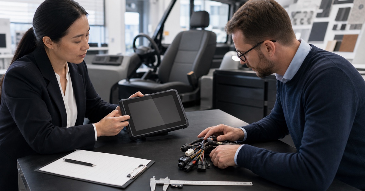

A CAN Bus vehicle computer does more than expose a pair of CAN terminals. It has to receive the right messages at the right time, pass selected data to an application, coexist with serial devices and wireless links, and remain dependable across the vehicle's electrical and environmental conditions.
For OEMs, the difficult part begins after selecting a display size. Integration teams must agree on the bus architecture, message definitions, operating system interface, service behavior, and acceptance tests. This guide provides a practical checklist for turning a CAN Bus terminal into a repeatable production subsystem.
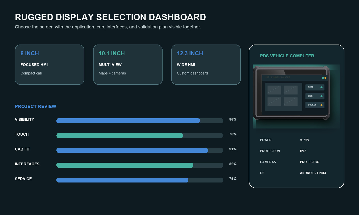
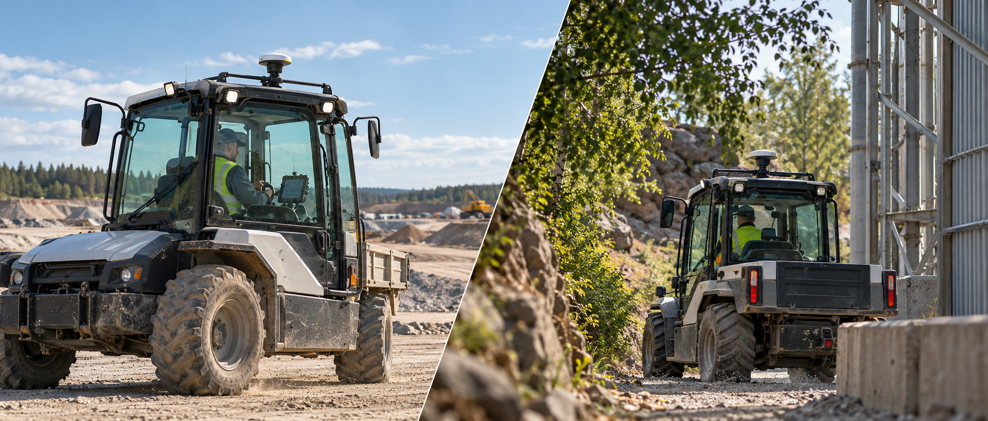
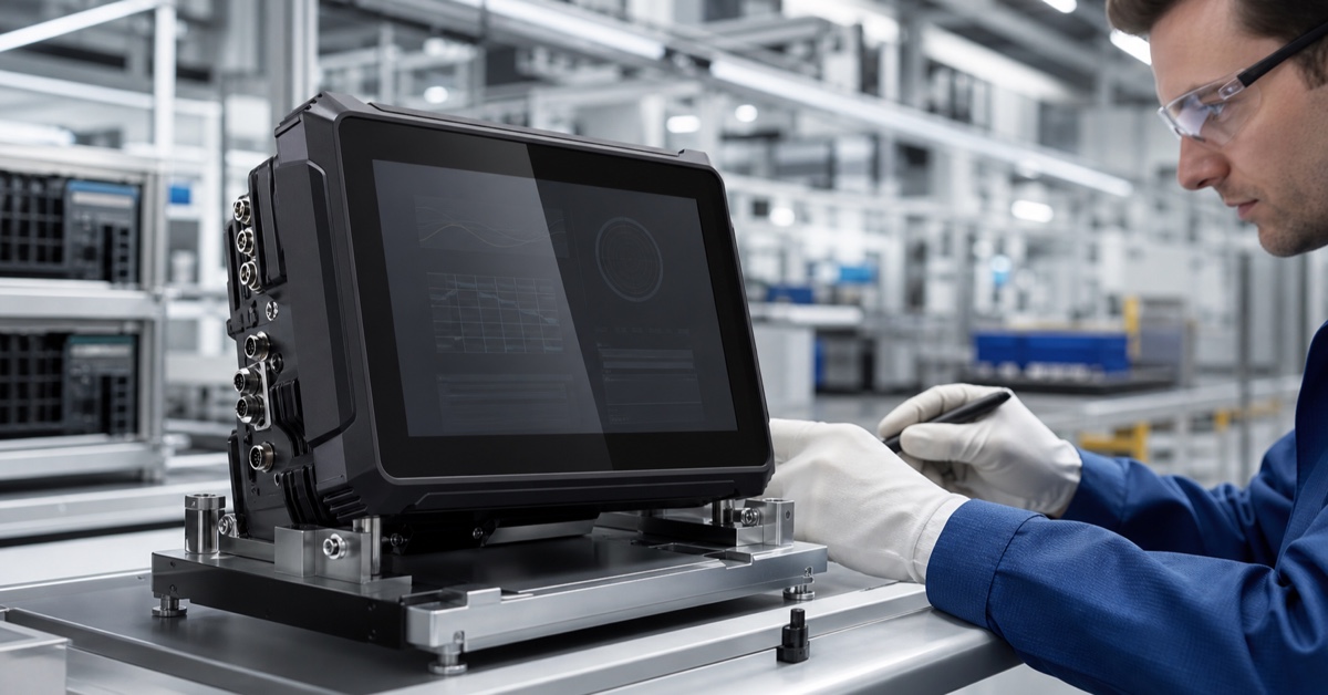
PDS integration illustration. Wiring, protocols, and software behavior must be validated on the target vehicle.
Define the CAN Bus vehicle computer architecture before choosing hardware
A CAN network is a shared differential bus. Multiple electronic control units exchange frames, and each receiving node decides whether a frame is relevant. The physical layer, bit rate, termination, connector policy, and message protocol must match the vehicle design. CSS Electronics provides a useful introduction to CAN Bus for teams that need a shared vocabulary.
The first OEM decision is what the CAN Bus vehicle computer is allowed to do. It may monitor data only, request a limited set of actions, act as a gateway, or participate in a private network. Write that role into the interface control document. A monitoring terminal and a command-capable controller require different testing and cybersecurity attention.
Also identify every bus connected to the terminal. Commercial vehicles often separate powertrain, body, implement, diagnostics, and private CAN networks. Mixing them without an isolation or gateway strategy can create unwanted traffic, wake-up behavior, or fault propagation.
| Integration layer | Design decision | Evidence required |
|---|---|---|
| Physical | Bit rate, topology, termination, cable, connector and isolation | Harness drawing, oscilloscope or analyzer capture and EMC plan |
| Protocol | Raw CAN, J1939, CANopen, ISO-TP, UDS or proprietary format | Message database, identifiers, timing and state diagrams |
| Operating system | Driver, API, permissions, process priority and recovery | SDK documentation, sample code and fault-injection results |
| Application | Decoding, filtering, logging, display and business logic | End-to-end test cases with recorded vehicle data |
| Lifecycle | Version control, updates, diagnostics and field service | Configuration baseline, release process and recovery procedure |
Complete a CAN Bus RS232 RS485 vehicle computer checklist
OEM projects often combine CAN with legacy serial equipment. A CAN Bus RS232 RS485 vehicle computer checklist should document each interface separately and then test the complete data path.
CAN Bus
Confirm the number of independent channels, CAN FD support, bit rates, termination method, isolation, wake behavior, and connector pinout. Verify whether the terminal must receive specific frames only or transmit messages as well. Capture bus load and worst-case latency with the complete vehicle harness.
RS232 and RS485
For a vehicle computer with RS232, specify voltage levels, baud rate, flow control, connector, cable length, and protocol. RS232 is commonly point-to-point. RS485 may use half-duplex or full-duplex operation with multiple nodes, so termination and bias requirements must be defined. Do not assume that identical baud settings guarantee protocol compatibility.
Request a loopback or device-level test before vehicle installation. Then test concurrent traffic across CAN, both serial channels, USB, and the wireless connection. Shared processor load and interrupt handling can reveal problems that do not appear in single-interface demonstrations.
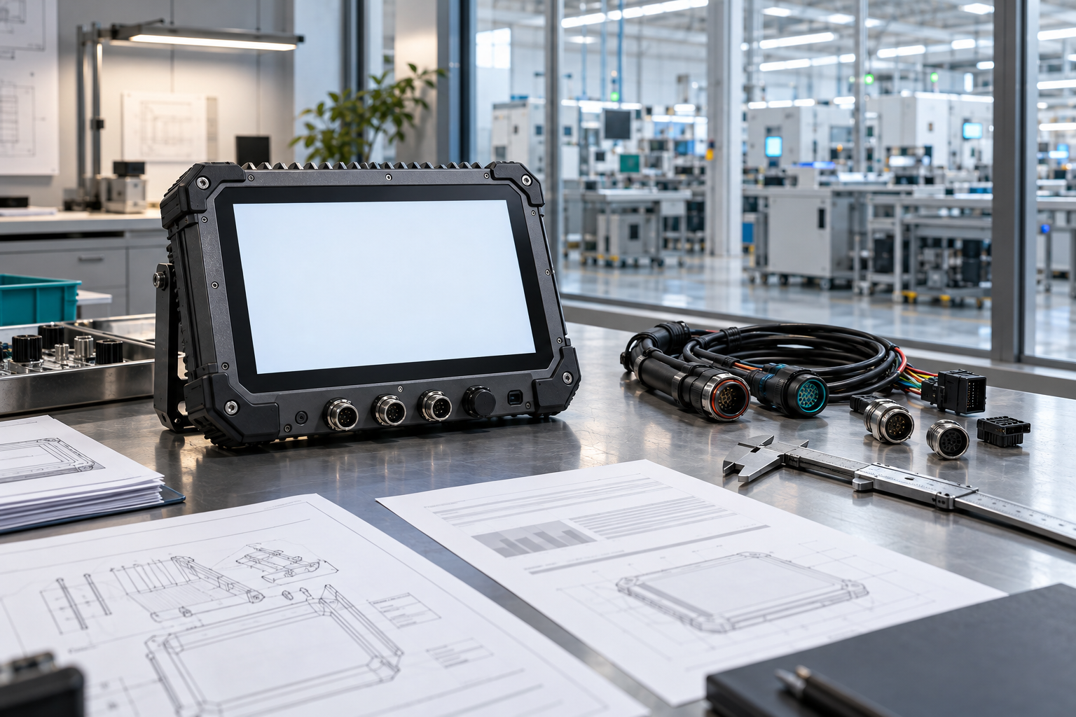
PDS OEM integration illustration. Interface behavior must be confirmed with the quoted product configuration.
Control the message database and data model
The application should not decode raw hexadecimal frames throughout the codebase. Define a message database or DBC, map physical values and units, and generate a tested decoding layer. Include update rates, timeout behavior, invalid-value handling, byte order, scaling, and signal ranges.
Version the database with the vehicle software, not only with the terminal application. If an ECU adds a message or changes a signal, the integration team must know which terminals, cloud models, and test cases are affected. Store representative CAN logs so decode changes can be replayed without a vehicle.
If the project uses SAE J1939, document the source addresses, parameter groups, request behavior, and diagnostic handling. For CANopen or a proprietary protocol, provide equivalent state machines and error definitions.
Select the operating system and CAN API
A CAN Bus vehicle computer running Linux can expose its interfaces through the kernel's SocketCAN subsystem. The software team can use standard socket operations, filters, and network tools. Confirm the kernel version, CAN driver, receive buffer configuration, and permissions in the shipping image rather than only in a development board.
On Android, the supplier may provide a Java, Kotlin, native, or JNI API. Ask how applications receive frames, how transmit access is controlled, and what happens when the service restarts. The integration plan should include a watchdog or health check that can recover from a stopped process, a disconnected interface, or an error-passive bus state.
OpenHarmony projects should receive an equally specific interface definition. Avoid accepting a generic statement that CAN is supported. The OEM needs the actual API surface, sample project, permissions, lifecycle behavior, and debuggability.
Add GNSS and 4G LTE without weakening the vehicle interface
A GNSS vehicle terminal with CAN Bus can combine position, motion, and vehicle-state data. Define the required accuracy, update rate, coordinate format, time source, and correction service. Test antenna placement with the real roof, cab, cargo, and nearby radio equipment. Keep GNSS loss and CAN timeout as independent states so one unavailable source does not invalidate the other.
A 4G LTE vehicle mounted computer extends those data streams to a fleet platform, but the uplink should not be treated as always available. Specify supported bands, carrier profiles, roaming behavior, antenna isolation, data limits, and reconnection time. Use local buffering for important records and define which fields are sent immediately, periodically, or only after an event.
Delimit data ownership and access. Vehicle owners may require control over location, diagnostics, driver, and operational data. The terminal and cloud platform need clear authentication, authorization, retention, and remote-command policies.
Protect power, signals, and the software boundary
Vehicle power includes cranking dips, load dump, jump starts, and accessory switching. The CAN Bus vehicle computer must be specified with an input range, transient standard, fuse, grounding, and ignition behavior for the actual vehicle class. CAN and serial ports may also require galvanic isolation or protection when they connect to external equipment.
Treat CAN as a trusted interface only after the OEM defines trust. Restrict transmit identifiers, validate received lengths and ranges, rate-limit commands, and prevent an application from accessing unrelated bus channels. Log security-relevant configuration changes and support signed or verified software updates.
The cable harness should support serviceability. Label connectors, document pinouts, protect unused ports, and specify torque where required. A terminal that passes on a bench can still fail if a heavy harness pulls on a connector or creates a stub that disturbs the bus.
Use an acceptance matrix for production release
| Test area | Example acceptance criterion |
|---|---|
| Bus health | No unintended error frames during normal, startup, wake, and shutdown sequences |
| Data accuracy | Decoded signals match reference measurements across the full operating range |
| Latency | Critical data reaches the application within the project's timing budget |
| Recovery | CAN, serial, GNSS, and cellular services recover after cable, power, and network faults |
| Power cycles | Configuration and buffered data survive the required ignition and battery scenarios |
| Update and rollback | A failed update can return the unit to a known serviceable version |
Before production, a CAN Bus vehicle computer should pass an approved matrix of bus, latency, recovery, and update tests. PDS provides OEM/ODM integration support for rugged vehicle terminals and can align interfaces with the project's software plan. The OEM should still own the vehicle-level interface specification and approve the final validation plan.
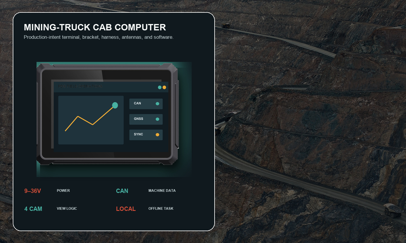
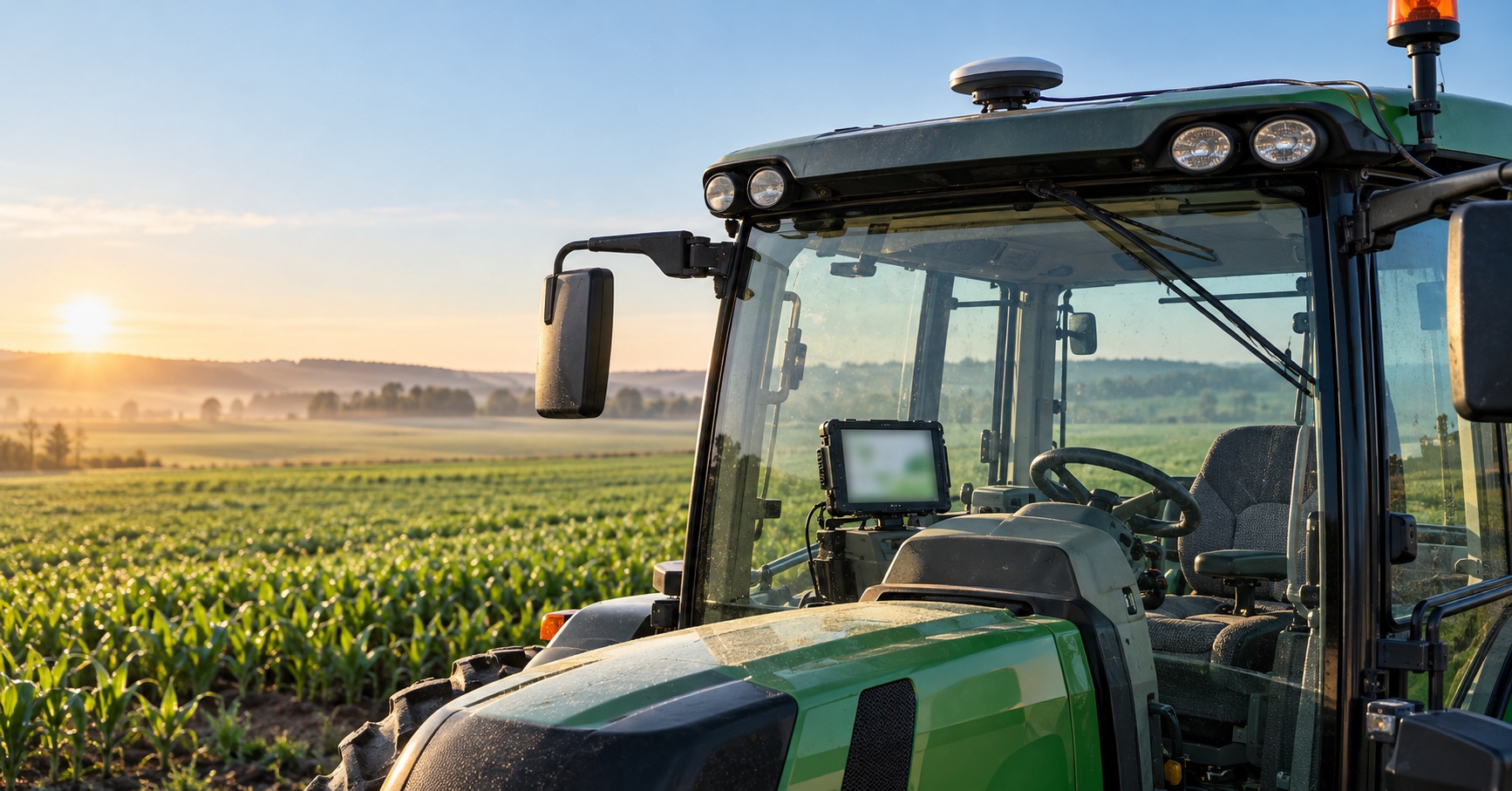
PDS validation illustration. Acceptance criteria and test equipment must be agreed before production release.
FAQs
What does a CAN Bus vehicle computer need to receive vehicle data?
It needs a compatible physical CAN interface, the correct bit rate and termination, access to the relevant bus, a message database, and software that decodes the required signals. The terminal must also handle timeouts, invalid values, and bus faults.
Can one vehicle computer use CAN, RS232, and RS485 at the same time?
Many rugged vehicle computers can support these interfaces concurrently, but the exact channel count and isolation depend on the model. Test all required traffic at the same time and confirm the operating system exposes each interface reliably.
Is J1939 the same as CAN Bus?
J1939 is a higher-layer protocol used on CAN networks, mainly in heavy-duty vehicles. A terminal can support CAN physically without supporting the specific J1939 messages or diagnostic behavior required by the project.
Should CAN data be processed on the terminal or in the cloud?
Use the terminal for time-sensitive filtering, display, alerts, and buffering. Send summarized or event-driven records to the cloud when network availability and data policy allow. The split should follow latency, privacy, cost, and offline requirements.
Contact us
📧Email:[email protected]
📞Tel:+86 13421822024
🌐Website: www.szpds.com
Disclaimer
The information in this article is for reference only. PDS Technology Co., Ltd. assumes no responsibility for errors, omissions, or suitability of the content for specific applications. Product specifications are subject to change without notice. Buyers should verify all technical details with our team before use.
About PDS Technology
PDS Technology is a leading OEM/ODM manufacturer of high-precision RTK GNSS terminals and vehicle computers, serving agriculture, construction, mining, taxi, and logistics industries since 2011.
With 15+ years of automotive-grade R&D experience, we offer rugged, multi-OS (Android/Linux/OpenHarmony) devices featuring RTK centimeter-level positioning, IP66 protection, and AI-ready performance. Our IATF16949-certified factories have produced over 100,000 units deployed globally, holding 30%+ of China's agricultural auto-steering terminal market. We export to Japan, the US, UK, Turkey, Russia, and beyond.