

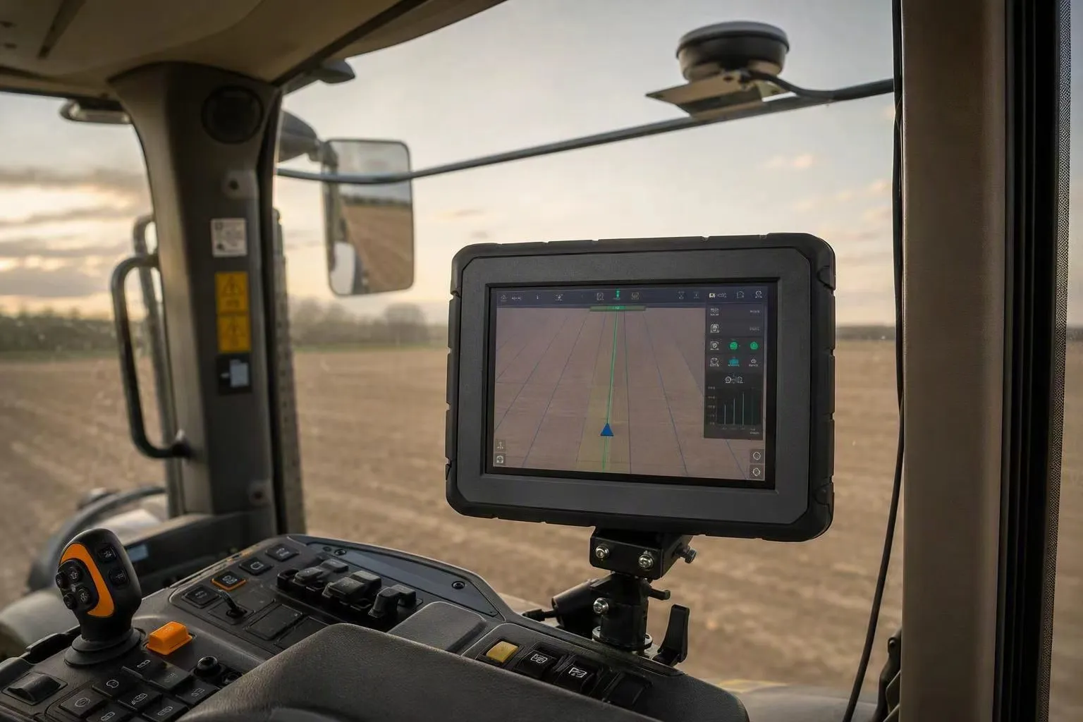
A vehicle mounted computer that can go a full season of auto-steering without an operator noticing a wander is not the one that tops the datasheet on accuracy. It is the one whose correction link can survive a bad afternoon.
That is the uncomfortable part of specifying positioning for agricultural machinery. Every terminal datasheet in this category says something like "RTK centimetre-level positioning." That sentence is true of a receiver, and it tells you almost nothing about what the machine will do when the correction stream stutters behind a tree line, when the modem re-registers on a rural cell, or when the ignition is cycled between two fields.
This article takes accuracy as settled and works on the part that is not: what passes through the system when the correction link degrades, and what evidence you should demand before you specify a positioning claim into a machine you will have to support for years.
Accuracy is the least useful number on the datasheet
RTK is a differential technique. A receiver on the machine measures carrier phase to the satellites; a reference station or a network service estimates the errors affecting that region and sends them to the machine; the receiver applies them and resolves the integer ambiguities in the carrier-phase measurements.
When those integers are correctly resolved, the system is in a fixed solution. When they are not resolved but corrections are still arriving, it is float. When corrections are not arriving at all, it falls back to standalone positioning in the range of a few metres.
The arithmetic of that chain is what matters, not the last number in it. A correction stream that is late, incomplete or absent does not produce a slightly worse centimetre figure. It produces a different solution state, and the accuracy moves by an order of magnitude.
So the first specification that actually means something is not "what accuracy does it deliver" but "which states does it pass through, how quickly, and what does the guidance system do while it is passing through them."
Pro Tip: Ask the supplier to state whether their accuracy figure refers to a fixed solution, and what the system degrades to when the correction link is interrupted. A supplier who can answer that in writing understands their own positioning chain.
The positioning chain, and where it breaks
It helps to stop thinking about "the GPS" and start thinking about a chain with five links that all have to hold at once:
- Satellites — enough of them, in a usable geometry above the machine.
- The reference source — a local base station on the farm or a subscription network service covering the field.
- The correction link — how the corrections travel from the source to the machine: cellular data over NTRIP, or a dedicated radio.
- The vehicle receiver — which turns satellite measurements plus corrections into a position estimate and reports a solution state.
- The terminal and the application — which consume that position, log it, and feed the steering system.
A vendor describes link 4 on the datasheet, because that is the component they sell. Field performance is usually decided by links 2 and 3, and the operator experiences it through link 5.
If you want the underlying mechanics in more depth, how a vehicle mounted computer and an RTK GNSS terminal fit together covers the chain end to end. The point here is narrower: links 2 and 3 are where the reliability question lives, and they are the ones you cannot inspect from a datasheet.
The three states, and what each one actually gives you
Three solution states matter, and the table below is the one worth keeping. It is also the table most supplier conversations skip.
| State | What it means | Accuracy band | What the operator sees |
|---|---|---|---|
| Fixed | Carrier-phase integer ambiguities resolved. The strongest RTK state. | Centimetre level under the stated conditions | The machine holds the line. Passes repeat. |
| Float | Corrections arriving, ambiguities not resolved. | Decimetre level, with wide variance | The line looks plausible and is not. Overlap and skip appear without a warning. |
| Single | No usable corrections. Standalone positioning. | Metre level, degrading further if sky view is poor | Guidance becomes advisory. The operator has to drive. |
Two things follow from that table.
First, float is the dangerous state, not single. Single announces itself — the machine visibly stops steering well and the operator takes over. Float can look almost normal while quietly putting the whole pattern centimetres to decimetres off, which is precisely the error a controlled-traffic or strip-tillage programme cannot tolerate.
Second, fragility runs opposite to accuracy. Published GNSS analysis on a large highway dataset found that availability and continuity break down differently by position type, and that the states rank in inverse relation to accuracy: fixed is the most accurate and the most transient, while standard code-phase positioning is the least accurate and the most durable.
The article is worth being precise about what that source does and does not say. It reports availability and continuity broken down by satellite visibility, satellite geometry, position type (RTK fixed, RTK float, or standard positioning) and RTK correction latency over the network — Standalone and RTK GNSS on 30,000 km of North American Highways, ION GNSS+, 2019.
It is a highway study, not an agricultural one, and it does not provide field-outage durations for a tractor in a maize canopy. What it does support is the mechanism: latency over the network and solution type both bear on whether a fixed solution is available at any given moment.
If you have ever wondered why a system that scores beautifully on a test track can be unreliable across a season, this is the reason. You are not buying accuracy. You are buying how long the system holds its most accurate state.
Where the correction link actually breaks
Six failure modes account for most of the trouble in the field. None of them are visible on a datasheet.
Baseline distance. Accuracy degrades with distance from the reference station because atmospheric errors decorrelate over distance. Practical RTK deployments are generally treated as local: the commonly cited working range for a local base station is on the order of 10 km or so, which is a design constraint to confirm rather than a universal law. Network RTK exists to extend coverage by modelling the regional error field rather than broadcasting one station's corrections. If a supplier quotes a single accuracy figure without stating the baseline it was measured at, the figure is not comparable to anything.
Correction latency and age of differential. Corrections describe the state of the ionosphere and troposphere at the moment they were generated. The older the correction, the less it describes the present. A network link that adds buffering, retries or route changes raises the age of the differential, and the receiver responds by being less willing or less able to hold a fixed solution. Latency is a network property, not a receiver property, and it is the reason a terminal can behave differently on two farms with the same hardware.
Packet loss and brief outages. NTRIP over cellular is a stream over an unreliable transport. Short dropouts are normal in rural coverage. A receiver that loses corrections for a few seconds does not merely hold its last position — it loses the ambiguity resolution and has to reconverge.
The rover's uplink. With many network correction services, the machine must send its approximate position back to the service, conventionally as an NMEA GGA sentence, so that the service can locate it in its network model and stream corrections matched to that location. If GGA upload is disabled, misconfigured, or interrupted, the service may authenticate the connection and then send nothing useful. This is a genuinely in-the-cab failure mode: it is a setting on the terminal or in the application, and it can be introduced by a firmware update or a configuration change that nobody connects to a positioning complaint.
Multipath and the antenna environment. The machine is a set of large reflective metal surfaces, and the antenna sits on top of them. Reflected signals arriving out of phase with the direct signal bias the carrier-phase measurement rather than merely adding noise to it. Carrier-phase multipath is bounded and generally smaller than code multipath, but it is not negligible relative to the centimetre errors being defended, and it is enough to disturb ambiguity resolution. Siting — height above the structure, a suitable ground plane, separation from the machine's own radio antennas, and a cable run that is short or at least loss-controlled — is part of the positioning specification, not a mechanical afterthought.
Rural network coverage and subscription dependence. The correction path is a dependency on infrastructure the machine operator does not control: cell coverage at the field edge, a mountpoint on a caster, credentials that can expire, and a data plan that has to be maintained. NTRIP is a protocol carried over the internet, and the RTCM message set is the payload — a modern RTCM 3.x stream carries multiple-signal observation messages plus metadata that can identify the antenna, and the RTCM 3 message list is a reasonable way to see what a stream actually contains. The practical question for procurement is not which message types exist but which of them your chosen service actually emits, and what happens to the machine when the subscription lapses mid-season.
Re-convergence: the part nobody puts in the brochure
When the correction link comes back, the receiver does not snap instantly to a fixed solution. It has to re-acquire the ambiguities. In practice this takes anywhere from a few seconds to a couple of minutes depending on receiver quality, sky view and how fresh the corrections are.
During that window the system is in float or single, and the guidance system — if it is steering at all — is working from a worse position than it was a minute earlier.
In the field this looks like a machine that drifts off the line at the headland, corrects itself a row later, and produces a strip of overlap nobody attributes to anything. For a worked example of how guidance work actually sits on a vehicle terminal through the season, agricultural auto-steering deployment is a reasonable starting point.
There is a second re-convergence event that agricultural machinery generates far more often than survey equipment does: the ignition cycle. Terminals are vehicle-powered, so every shutdown between fields, every refuelling stop and every overnight park is a power interruption.
What happens next depends entirely on the terminal's behaviour — whether it retains the receiver state, whether the application re-establishes the correction session automatically, whether credentials survive a cold start, and how long the operator waits before the machine is usable again.
This is where a terminal's integration matters more than its receiver. The design question to put to any supplier is blunt: describe the exact sequence after an ignition cycle, from power-on to a fixed solution, including who or what re-establishes the correction session.
Pass-to-pass and absolute accuracy are not the same number
How accuracy is defined causes more specification arguments than any other topic in this category, and it is worth settling before you compare suppliers.
Pass-to-pass accuracy describes how closely the machine repeats a line relative to a recent adjacent pass. In the standard formulation used in the extension literature, it is related to the expected skips and overlaps between two passes within a 15-minute interval, and the claimed error should not be exceeded 95% of the time. That framing comes from Satellite-Based Auto-Guidance (Adamchuk, University of Nebraska–Lincoln Extension, EC706, 2008), which is also the source of two cautions worth repeating: the two error families — pass-to-pass and year-to-year — behave differently, and the exact definition of pass-to-pass error may vary from vendor to vendor.
Year-to-year accuracy describes whether the machine returns to the same geometry in a later season. It is the number that matters for controlled-traffic farming, strip tillage and anything requiring a new operation to sit in a strict geometrical relationship to previous tracks.
Absolute accuracy describes how close the reported position is to a true coordinate reference frame. A system can repeat its own passes beautifully while the entire pattern is offset from the map — consistent, and consistently in the wrong place.
| What you need to do | Which figure answers the question |
|---|---|
| Reduce overlap and skip across adjacent passes within a job | Pass-to-pass |
| Return to the same tramlines or beds next season | Year-to-year |
| Match a surveyed boundary, map or as-applied record | Absolute |
| Hold a heading at low speed or when stationary | Not an accuracy figure at all — a dual-antenna or IMU question |
A supplier who answers "2 cm" to a question about which figure they mean has not answered the question. Ask for the definition, the interval, the statistical basis (mean, RMS, 95th percentile, or maximum) and the conditions — because "2 cm" without those four is not a specification, it is a slogan.
If you searched for "vehicle mount tablet"
The term is worth resolving early, because a large share of searches for in-cab displays land on the wrong category.
A vehicle mount tablet is a consumer or light-commercial product: a bracket, a cradle or a holder that takes a tablet someone already owns and fixes it inside a vehicle. The search results for that term are dominated by cup-holder mounts, seat-rail brackets, suction mounts and ELD holders. They are mounting hardware. They have no vehicle power input stage, no transient protection, no machine interfaces and no configuration for a correction path.
A rugged vehicle computer — also sold as a vehicle-mounted terminal or vehicle mounted computer — is a different device. It is designed to be installed in the machine, powered from the vehicle's electrical system, mounted permanently, and connected to the machine's networks and to a positioning receiver through defined interfaces. It is specified, tested and supported as equipment rather than as an accessory.
The two are not interchangeable, and the confusion matters for two reasons. A bracket does not solve a positioning problem — the correction link, the receiver state and the antenna siting are all upstream of whatever holds the screen. And a bracket does not solve a durability problem either: an accessory rated for cabin comfort is not the thing to specify into a machine that will spend a decade in dust, vibration and rain.
If a specification or a query conflates them, resolve it early. The correct vocabulary for this audience is vehicle-mounted terminal, in-cab terminal or vehicle computer — the mounting hardware is a separate line item.
Interfaces and the machine side
Positioning is delivered to the machine as data, and where that data goes is part of the specification.
The interfaces to confirm are the ones the application needs rather than the longest list available: CAN bus — including whether the terminal exposes it as a network interface with the socket CAN API, which matters for how much integration work you inherit — serial ports such as RS232 and RS485 for legacy controllers and correction radios, Ethernet where a sensor network already exists, and cellular, Wi-Fi and Bluetooth for the correction path and for service access.
A terminal that supports RTK positioning and exposes dual CAN plus serial ports, such as the T10Pro 10-inch vehicle computer, can carry positioning, machine data and the operator display in one unit, which removes a separate display from the integration and one more connector from the vibration problem.
That is one worked example inside the criteria, not an argument. The criteria are the same for any supplier: which correction path is supported, how the session is re-established after a power cycle, how the solution state is exposed to the application, and what happens to the guidance output when the state degrades. RTK GNSS vehicle terminal solutions shows how the positioning side is typically packaged for auto-steering work.
The procurement and compliance checklist
Engineering gets most of the positioning discussion. Procurement owns the risk, and "we support RTK" answers none of the questions below.
- EU technical documentation. Can the supplier provide technical documentation suitable for your own CE obligations, and does it state the standards and test conditions the product was assessed against?
- EMC context, correctly scoped. For agricultural machinery, the relevant EMC standard for the machine is ISO 14982, which specifies test methods and acceptance criteria for the electromagnetic compatibility of tractors and mobile agricultural, forestry, landscaping and gardening machinery — ISO 14982:1998, still current at its last review in 2014. Note what that scope means: it applies to the machine as supplied by the machine manufacturer. It is not a component-level certificate you can inherit, and a supplier claiming EMC compliance should be able to explain how their component was assessed and against what.
- Correction-path dependency. Which correction services and message types are supported in the shipped configuration, and what is the fallback behaviour if the subscription is unavailable?
- Exposing the solution state. Can the application read the solution state, or only a position? A system that cannot report that it is in float cannot be monitored for it.
- Behavioural documentation. A written statement of correction-loss behaviour: how long the fix is held, what the state sequence is, and what the guidance output does — as a specification you can test against, not a verbal assurance.
- Antenna and cabling as a specified assembly. Which antenna, what ground plane, what cable and what connector, and is the installed assembly the one that was tested?
- Long-term supply and service. For a machine supported across multiple seasons, the positioning receiver and antenna must be obtainable as spares, and the correction configuration must survive a firmware update.
The PDS rugged vehicle terminal range is one place to see how these items are presented for a family of terminals, including the series in different screen sizes for different cab and machine layouts.
How to verify a positioning claim in one day
You do not need a test range to find out whether a claim survives contact with your own machine. You need one field, one day and a log.
- Run on your own machine, with your own correction source. Not a demo unit, not the supplier's service. The correction path is the variable under test.
- Log the solution state, not just the position. Fix type, time to first fix, and the state history across the run. Without the state history you cannot distinguish a good fix from a confident float.
- Measure the ignition cycle. Time from cold start to fixed solution, repeated three times, with the application launched the way an operator will launch it.
- Test across the worst part of the day and near the field boundary. Satellite geometry varies with time — low satellite count and poor spread raise the dilution of precision and will show up as a state change. Fields with a tree line on the edge are the honest test.
- Break the link deliberately. Power down the reference source or disconnect the data path, note what the terminal reports, how long the fix is held, what the guidance system does, and how long reconvergence takes once the link returns.
- Run repeat passes and measure the deviation yourself. Adjacent passes within 15 minutes for the pass-to-pass behaviour, and a return to the field on a later day for the year-to-year question. Compare against a surveyed marker if you have one.
- Confirm the degradation is visible. If the operator cannot tell from the terminal that the system is in float, that is a finding, and it belongs in your risk assessment rather than in a bug report.
Two cautions. A single good day does not establish a season, so run the test in the conditions that actually break the system — canopy, boundary, bad weather, the time of day with the worst geometry. And record the antenna installation in the same session; if the assembly moves, the result is no longer comparable.
⚠️ Warning: Never accept a bench test as evidence of field performance. A terminal that holds a fixed solution indoors, with no canopy, no machine structure and a short cable to a reference antenna, has demonstrated nothing about a machine working a field edge under a tree line.
Verifying the rest of the terminal — display behaviour, power stage and enclosure — on the same machine is a separate exercise with its own checklist.
It matters, but it does not change the answer you get here: a rugged vehicle computer with a superb display and a power stage that survives every transient is still a guidance liability if nobody can tell when it drops out of a fixed solution. Run the positioning test first. It is the one that decides whether the system you are specifying can be trusted across a season, and it is the one no datasheet will answer for you.
FAQ
Is "2 cm accuracy" a promise or a condition?
A condition, and an incomplete one. It describes a fixed solution under specific conditions, measured at a specific baseline, reported against a specific statistical basis. Ask which of pass-to-pass, year-to-year or absolute accuracy is meant, over what interval, and whether the figure is a mean, RMS, 95th percentile or maximum. A number without those attached cannot be compared with another supplier's number.
Why does my RTK drop to float at the headland?
Usually a combination of transient satellite geometry and a local obstruction — the machine turning under a tree line, a gradient change, or the antenna briefly seeing more reflected signal. Shorter baselines, a better antenna installation and a receiver with stronger ambiguity resolution all reduce the frequency, but none remove it. What matters operationally is whether the terminal reports the state change.
Does a longer baseline only reduce accuracy, or does it also lose the fix?
Both, and the second is the problem. Distance decorrelates the atmospheric errors the corrections are modelling, which degrades accuracy and makes ambiguity resolution progressively harder to hold. This is why local base deployments are treated as local, and why network services model a region rather than broadcasting one station.
Are power banks relevant to any of this?
No. Vehicle-mounted terminals in this class are vehicle-powered and are not carried off the machine, so a portable power source is not part of the installation. Where backup power matters, it is a machine-level electrical question — the terminal's own power input stage and how it handles supply transients — not a battery accessory.
Can I rely on the correction service provider for the accuracy figure?
Not on its own. The provider controls the correction stream; the receiver, the antenna installation, the terminal configuration and the machine's electromagnetic environment all sit on your side of the boundary. A service specification tells you what is being broadcast, not what your machine achieves.
Where to go from here
The rule that survives every supplier conversation is this: treat the accuracy figure as the outcome of a system, and treat the reliability figure as the specification you actually buy. The reliability figure is expressed as behaviour — the states the system passes through, how long it holds its most accurate one, how quickly it recovers, what the operator can see while it recovers, and what the machine does across an ignition cycle.
Ask for that behaviour in writing. Then go and test it on your own field, with your own correction source, on a day when the geometry is not in your favour. A supplier who understands positioning will welcome the test, because a system that behaves predictably at float is easier to sell than a claim that has to be taken on trust.
Contact us
📧Email:[email protected]
📞Tel:+86 13421822024
🌐Website: www.szpds.com
Disclaimer
The information in this article is for reference only. PDS Technology Co., Ltd. assumes no responsibility for errors, omissions, or suitability of the content for specific applications. Product specifications are subject to change without notice. Buyers should verify all technical details with our team before use.
About PDS Technology
PDS Technology is a leading OEM/ODM manufacturer of high-precision RTK GNSS terminals and vehicle computers, serving agriculture, construction, mining, taxi, and logistics industries since 2011.
With 15+ years of automotive-grade R&D experience, we offer rugged, multi-OS (Android/Linux/OpenHarmony) devices featuring RTK centimeter-level positioning, IP66 protection, and AI-ready performance. Our IATF16949-certified factories have produced over 100,000 units deployed globally, holding 30%+ of China's agricultural auto-steering terminal market.We export to Japan, the US, UK, Turkey, Russia, and beyond.