
A construction equipment GNSS terminal can support far more than a dot on a map. Depending on the receiver, antenna, correction service, machine interfaces, and application, it may provide fleet location, zone events, route history, guidance, measurement support, or higher-accuracy positioning. The word “GNSS” alone does not define the result.
A reliable project begins by writing the positioning job in operational language. State who uses the position, what decision it supports, the required accuracy and update rate, where the equipment operates, how long communication can disappear, and what should happen when the position becomes uncertain.
1. Choose the positioning outcome first
General fleet location may tolerate meter-level position and occasional communication gaps. A zone-entry alert needs stable boundaries and a clear rule for poor accuracy. Guidance or measurement work may demand much tighter accuracy, a correction source, careful antenna placement, and explicit behavior when corrections are lost.
Write separate requirements for horizontal accuracy, vertical accuracy, update rate, startup time, heading, timestamp, and availability where they matter. Avoid one vague statement such as “centimeter-level GNSS” without defining the conditions and recovery behavior.
2. Understand the complete signal chain
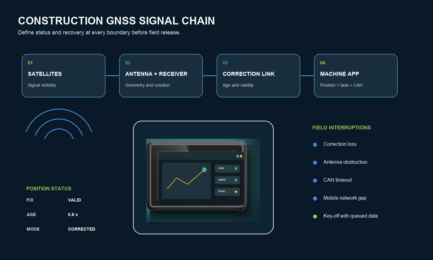
The final position comes from satellites, the antenna, cable, receiver, optional correction data, mounting geometry, software filtering, and the application. A weakness anywhere in that chain can limit performance. The vehicle terminal also needs to associate the position with machine identity, time, task, and possibly CAN or sensor records.
Document which component produces the GNSS solution and which component owns the application. Confirm the data format, update rate, coordinate system, correction protocol, ports, cable lengths, timestamps, and error states before the harness is released.
3. Antenna placement changes the result
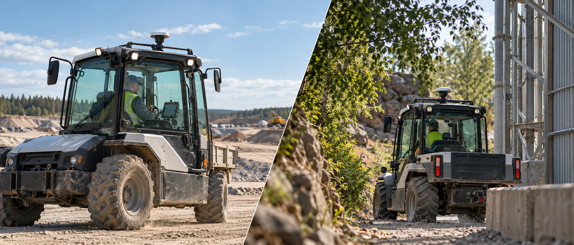
The antenna needs a useful view of the sky, a rigid mounting surface, suitable ground-plane conditions where required, and separation from strong interference sources. It should not be placed casually under a roof edge, close to a moving boom, or beside equipment that repeatedly blocks satellites.
Construction machines change orientation and articulation throughout the shift. Excavator booms, dump bodies, cranes, and nearby rock walls can alter visibility. Test in the positions that matter, not only with the machine parked in an open yard.
4. Correction services and communication
Higher-accuracy applications may receive corrections by radio, cellular network, or another project-specific path. Define the supported protocol, region, subscription or base-station responsibility, expected latency, authentication, and what the user sees when corrections age or stop.
Do not allow a stale high-accuracy status to remain on the screen. The application should distinguish valid correction, degraded solution, standard GNSS, and no reliable position. Log these transitions so field teams can separate coverage issues from receiver or installation issues.
5. Connect position with machine data
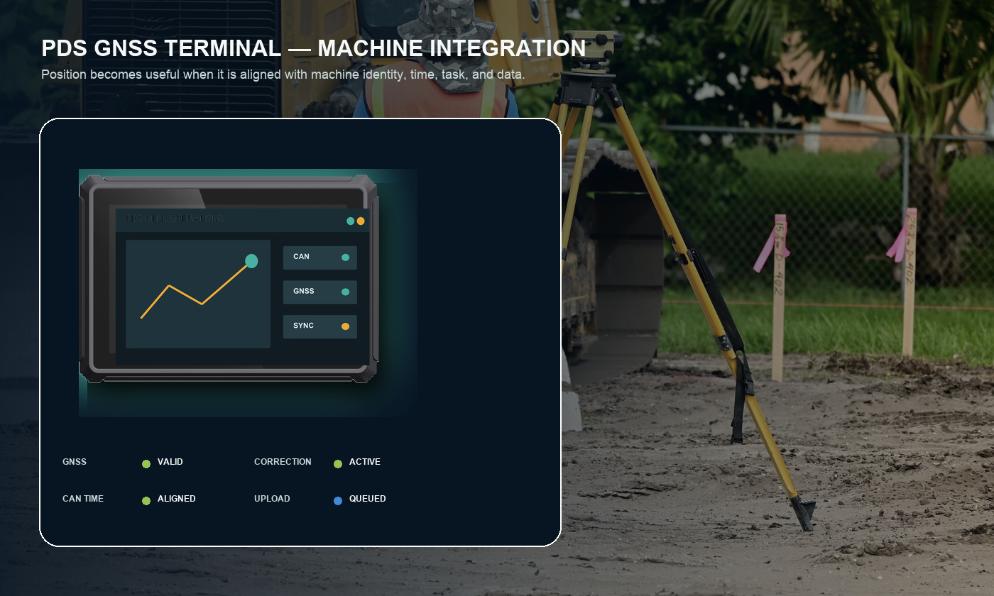
Position becomes more useful when it is paired with the correct machine event. CAN, RS232, RS485, Ethernet, USB, and GPIO may connect engine state, hydraulic status, implement position, external sensors, cameras, or local controls. Confirm electrical details and data ownership before deciding that an interface name equals compatibility.
For CAN, define bitrate, termination, isolation, channel count, message identifiers, scaling, timeouts, and invalid-value behavior. For serial data, define voltage level, baud rate, protocol, connector pins, cable length, and grounding. Timestamp alignment deserves specific testing when data will be replayed or analyzed together.
6. Offline records and recovery
A construction equipment GNSS terminal should continue the agreed local workflow when mobile coverage disappears. Keep essential tasks, maps, configuration, and event records locally. Decide how much history is required, how storage limits are reported, and how uploads resume.
Use stable identifiers and timestamps so queued records do not become duplicates. Test a network loss during an active job, a power-off with unsent data, and a configuration update interrupted halfway through. Recovery should be visible and predictable.
7. Hardware requirements around the GNSS function
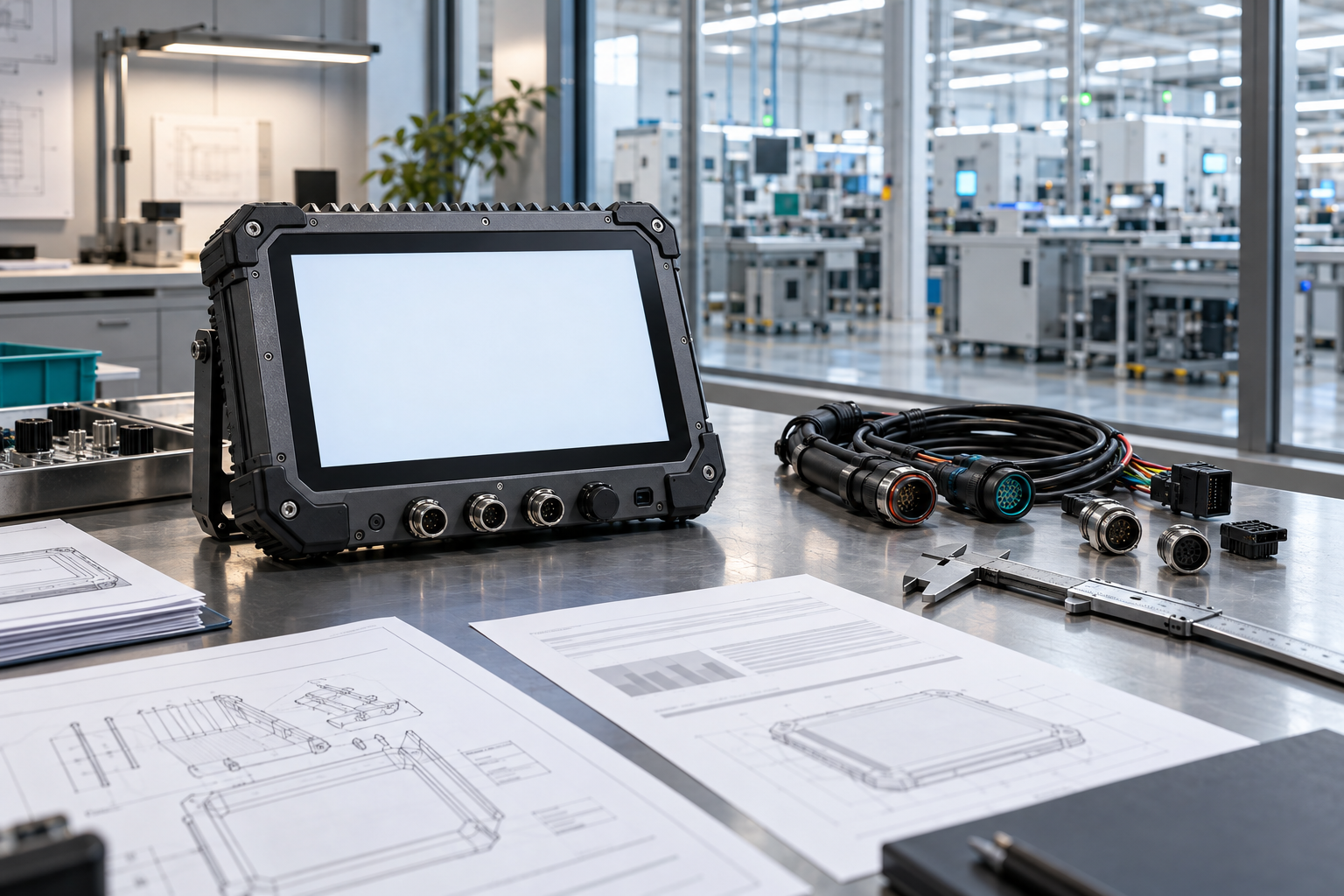
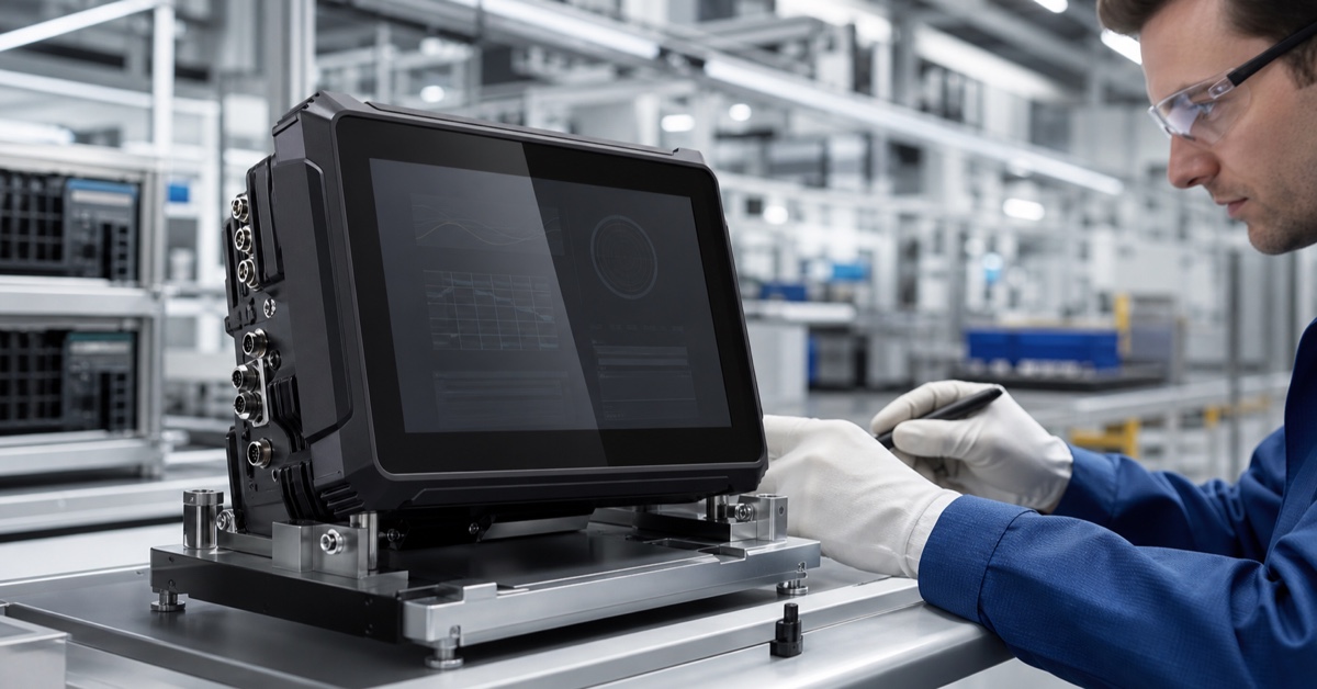
The computer still has to survive the machine environment. Review sunlight readability, touch operation, bracket stiffness, connector sealing, dust, water, temperature, vibration, vehicle power, boot time, and controlled shutdown. A precise receiver cannot rescue a display that the operator cannot read or an application that loses its current job.
PDS T8Pro and T10Pro configurations list IP66 protection, a -20°C to +70°C operating range, and 9–36V DC input. The quoted receiver, antenna, modem region, harness, connectors, OS image, and application must still be documented as one production configuration.
8. PDS options to discuss
| Application | PDS option | Integration discussion |
|---|---|---|
| Compact equipment HMI and GNSS application | T8Pro | 8-inch cab fit, configurable I/O, Android application, external or project-defined GNSS option |
| Larger map, machine data, or multi-view layout | T10Pro | 10.1-inch display, dual CAN, serial interfaces, cameras, optional RTK |
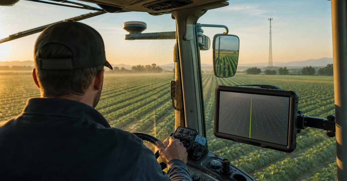
| Agricultural or guidance-focused RTK project | PDS precision agriculture platform | RTK correction path, antenna installation, guidance workflow, vehicle interfaces |
9. Validate position on the target machine
Test open sky, pit walls, tree lines, structures, parked equipment, machine articulation, and the normal route. Record solution status, satellite visibility where available, correction age, position repeatability, recovery time, and the application response. Repeat after the antenna cable and final bracket are installed.
Interrupt the correction link, antenna signal, CAN source, mobile network, and vehicle power separately. The operator should receive a clear status, and the application should avoid presenting uncertain information as confirmed.
10. Application examples
Zone-based equipment records
The terminal associates position with machine identity and a defined operating state. It stores zone entry and exit locally when the network is unavailable, then synchronizes the event history later.
Guidance or measurement support
The system uses a documented receiver, antenna, correction source, coordinate frame, and accuracy status. When corrections stop, the application changes status clearly and prevents the degraded position from being treated as approved work.
Frequently asked questions
Does every construction machine need RTK?
No. Fleet location and broad geofencing may use standard GNSS. RTK is relevant when the workflow needs higher accuracy and the project can support corrections, antenna placement, coordinate management, and field validation.
Can the GNSS antenna be mounted inside the cab?
Usually the project should prefer a location with a clear sky view and suitable mounting conditions. Cab glass, metal structures, roofs, booms, and nearby electronics may reduce performance. Test the proposed position.
How should GNSS and CAN records be synchronized?
Define the timestamp source, update rates, buffering, and message timeouts. Then test replay or analysis with real data to confirm that position and machine events remain aligned.
Specify the result, not only the receiver
A successful construction equipment GNSS terminal project defines the positioning outcome, full signal chain, machine interfaces, operator status, offline behavior, and recovery limits. Validate those items on representative equipment before freezing the hardware and software.
Review the PDS construction and mining solution, explore PDS RTK and precision-positioning experience, compare the vehicle computer range, or contact PDS Technology with your accuracy, interfaces, antennas, correction source, and application requirements.
Contact us
📧Email:[email protected]
📞Tel:+86 13421822024
🌐Website: www.szpds.com
Disclaimer
The information in this article is for reference only. PDS Technology Co., Ltd. assumes no responsibility for errors, omissions, or suitability of the content for specific applications. Product specifications are subject to change without notice. Buyers should verify all technical details with our team before use.
About PDS Technology
PDS Technology is a leading OEM/ODM manufacturer of high-precision RTK GNSS terminals and vehicle computers, serving agriculture, construction, mining, taxi, and logistics industries since 2011.
With 15+ years of automotive-grade R&D experience, we offer rugged, multi-OS (Android/Linux/OpenHarmony) devices featuring RTK centimeter-level positioning, IP66 protection, and AI-ready performance. Our IATF16949-certified factories have produced over 100,000 units deployed globally, holding 30%+ of China's agricultural auto-steering terminal market. We export to Japan, the US, UK, Turkey, Russia, and beyond.