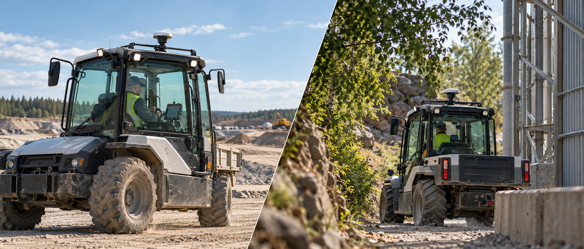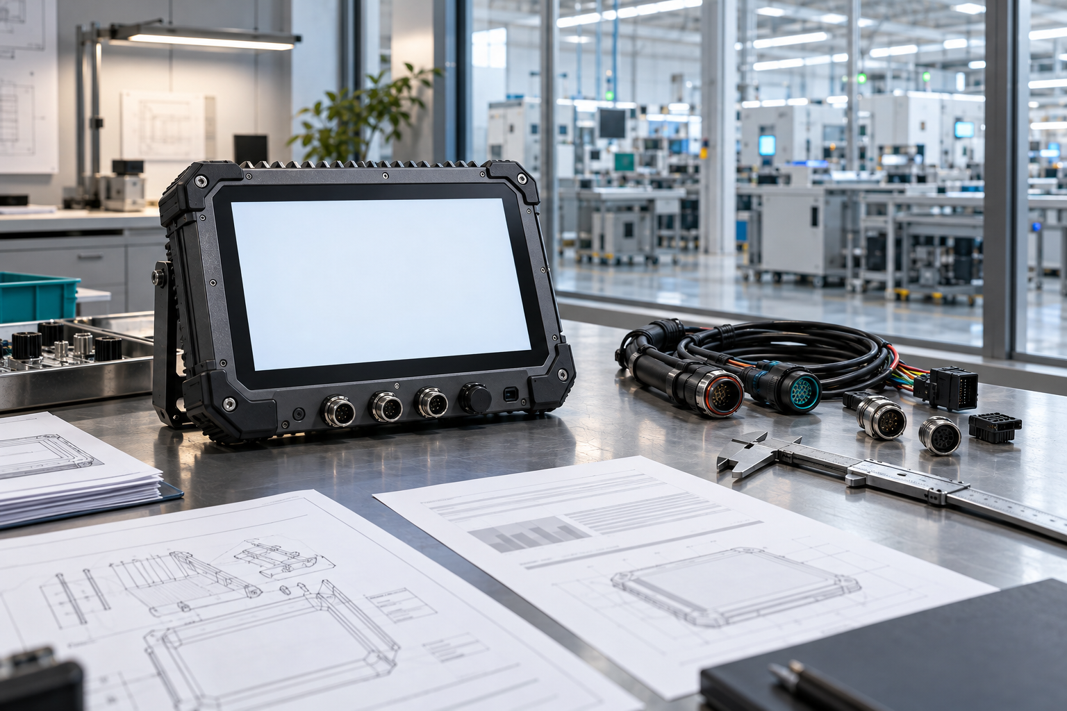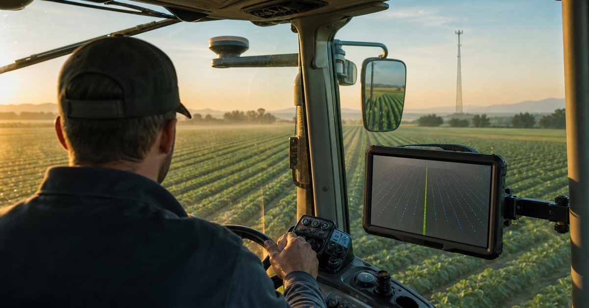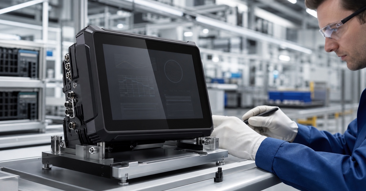

An RTK GNSS rugged vehicle terminal is more than a satellite receiver bolted to a dashboard. It combines high-precision positioning, an operator display, vehicle power management, communications, and machine interfaces in one fixed device. That combination matters on tractors, graders, excavators, mining vehicles, and other machines where the position must remain useful while the vehicle vibrates, works in dust, or moves beyond reliable cellular coverage.
The short explanation is this: GNSS provides the satellite measurements, RTK adds correction data, and the vehicle terminal turns the resulting position into something the operator or control system can use. A complete project still needs the right antennas, correction source, software, mounting, wiring, and fallback behavior. Buying an RTK-capable module alone does not finish the system.
What is an RTK GNSS rugged vehicle terminal?
A standard navigation receiver may be adequate for dispatch, route display, geofencing, and general vehicle tracking. Precision work is different. Tractor guidance, auto-steering, grading, machine control, repeatable field operations, and some survey-related tasks require much tighter and more consistent positioning.
RTK, or Real-Time Kinematic positioning, uses carrier-phase measurements together with corrections from a local base station or a network service. The high-precision positioning overview published by u-blox explains that the receiver, RTK algorithm, antennas, and correction data all form part of the solution. Depending on the design and conditions, that system can produce centimeter-level position information for a moving rover.
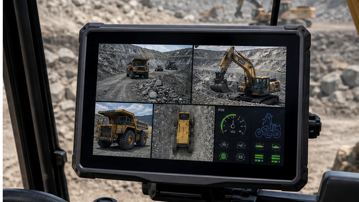
The rugged terminal is the in-cab part of that chain. It may display guidance lines, correction status, machine data, camera views, alarms, or work records. It can also exchange information with a steering controller, ECU, implement, modem, radio, cloud platform, or other equipment through CAN, serial, Ethernet, USB, 4G, Wi-Fi, or Bluetooth.
How RTK works on a vehicle
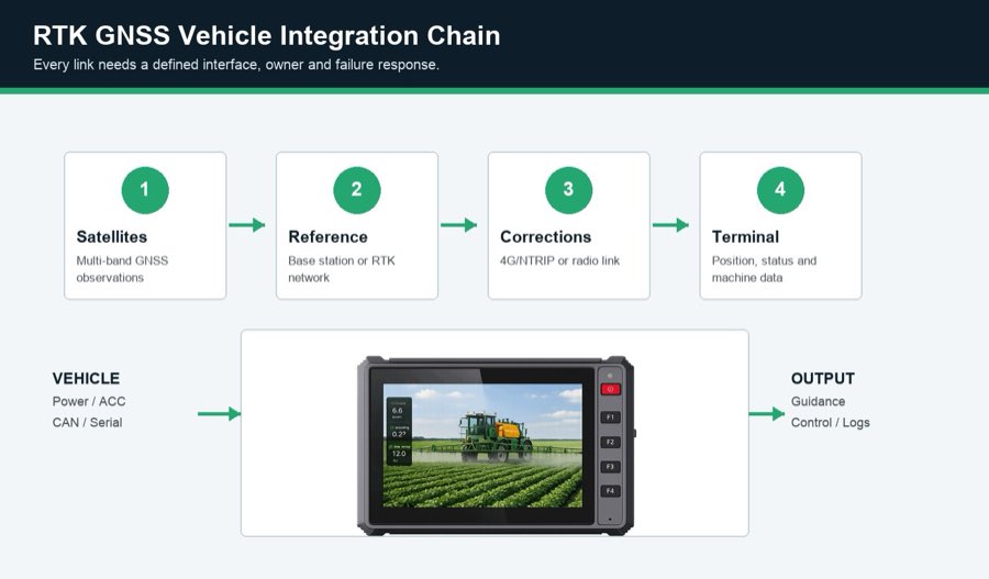
A practical RTK workflow has five stages.
- The GNSS receiver observes several satellite constellations. Multi-constellation and multi-frequency reception can improve availability, but the antenna still needs a clear view of the sky.
- A reference source estimates current errors. This may be a local base station, a regional RTK network, or another correction service.
- Corrections reach the vehicle. Common delivery paths include an Internet connection through 4G or a dedicated UHF radio. Coverage, data format, credentials, latency, and operating cost must be confirmed.
- The receiver calculates a high-precision solution. The application should distinguish fixed, float, differential, and standalone states rather than showing every result as equally reliable.
- The terminal passes position to the working system. Guidance software may draw a line, while an auto-steering controller uses heading, position, speed, and machine data to control movement.
Reference infrastructure is not theoretical. The NOAA Continuously Operating Reference Station Network, for example, distributes GNSS observations that help users improve positioning precision. Commercial RTK networks use a similar reference-station idea for real-time field services, although coverage and subscription arrangements vary by country.
The terminal cannot guarantee accuracy by itself
A specification such as “centimeter-level RTK” describes a capability under suitable conditions, not a promise for every installation. Trees, buildings, metal cab roofs, nearby radios, poor antenna cables, multipath reflections, a long baseline, correction latency, and weak satellite geometry can all change the result. So can software mistakes such as using the wrong coordinate system or treating a float solution as fixed.
Before deployment, define the result the operation actually needs. A sprayer may care about pass-to-pass repeatability. A grader may need vertical performance. A fleet platform may only need lane-level or meter-level location and gain little from an RTK subscription. The accuracy requirement should be written as an acceptance test, including the environment, speed, correction source, initialization time, outage duration, and allowed recovery time.
Key specifications that matter
| Specification | What to verify | Why it affects the project |
|---|---|---|
| GNSS/RTK receiver | Constellations, frequencies, RTK module, update rate, output protocols | Determines compatibility with the positioning design and application |
| Correction input | NTRIP or network service, radio option, RTCM compatibility, credentials | No correction path means no RTK fixed solution |
| Antenna system | Single or dual antenna, connector, cable loss, ground plane, mounting position | Installation quality can matter as much as receiver capability |
| Vehicle interfaces | CAN, RS232, RS485, Ethernet, GPIO, camera inputs, pinouts | Connects positioning with steering, sensors, cameras, and machine data |
| Power and ignition | Voltage range, surge protection, ACC behavior, delayed shutdown | Prevents resets, file corruption, and battery drain |
| Environmental design | Ingress rating, operating temperature, vibration evidence, connector sealing | Keeps the terminal usable in the actual vehicle environment |
| Display and controls | Brightness, optical bonding, touch behavior, buttons, mounting reach | The operator must read and control the system throughout the shift |
PDS RTK-capable terminal options
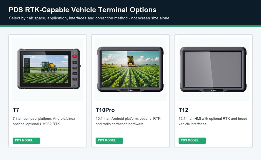
PDS Technology offers several vehicle-computer platforms that can be configured for RTK projects. The correct choice starts with screen space, software, interfaces, and installation constraints rather than the largest display.
| PDS model | Published starting point | Typical fit |
|---|---|---|
| T7 | 7-inch, Android or Linux, optional UM982 RTK, IP66, 9-36V DC | Compact cabs and focused guidance or machine-control screens |
| T10Pro | 10.1-inch, Android 11/13, optional UM482 or UM982 RTK, optional 410-470 MHz radio, IP66 | Agriculture, camera-rich fleets, and projects needing more application performance |
| T12 | 12.1-inch, Android or Linux option, optional UM982/UMD982 RTK, CAN/serial/Ethernet/camera interfaces, IP66 | Large tractors, combines, construction machines, and multi-window HMIs |
These published specifications are useful for shortlisting. The final configuration, module availability, software image, frequency band, cables, connectors, and certification documents should be confirmed with PDS before a purchase order.
Integration considerations before installation
Place the antenna before choosing the cable
Survey the roof and nearby metalwork. The antenna should have the clearest possible sky view, a stable ground plane where required, separation from high-power transmitters, and a route that protects the cable from sharp bends and moving joints. Record antenna height and offset if the control software uses them.
Define correction loss behavior
What happens after five seconds without corrections? The display may warn the operator, continue in a lower-accuracy state, pause automatic control, or follow another customer-approved rule. That decision belongs in the functional specification and the field test.
Confirm data ownership
List which device creates the position, heading, correction status, guidance line, steering command, work record, and cloud message. Then define the protocol and update rate for each connection. This prevents two devices from silently performing the same function or expecting different coordinate formats.
A practical field commissioning sequence
- Bench-test the selected receiver, correction source, application, and controller together.
- Install production-length cables and the intended antennas.
- Verify cold start, warm start, RTK initialization, and recovery after an obstruction.
- Drive beside buildings, trees, and field edges where multipath or satellite blockage is likely.
- Interrupt 4G or radio corrections and confirm the approved warning and fallback behavior.
- Cycle ignition repeatedly while logging position and application data.
- Compare repeat passes over known points, not just the position shown while stationary.
- Save the final firmware, configuration, cable drawing, antenna offsets, and acceptance results.
A 20-minute vehicle walk-around before the pilot
Before anyone opens a laptop, walk around the actual vehicle with the installer and the person who will use it. This short review often catches issues that a specification sheet cannot show. Start at the battery and follow the planned power route. Where will the fuse sit? Is the ignition signal easy to identify? Can a technician reach the connector without removing half the dashboard? These are ordinary questions, but they decide whether the first installation takes one hour or most of a day.
Next, sit in the normal driving position. Do not hold the terminal in your hand. Put a cardboard outline or sample unit where the bracket will be fixed. Check the windscreen, mirrors, controls, and the operator's knee clearance. Move the seat through its full range. Open the cab door. If the screen blocks a sight line or the cable rubs against a lever, change the location now. A larger display is useful only when the operator can see it without creating a new problem.
Then look at the roof. A convenient bolt hole is not automatically a good GNSS antenna position. Note nearby beacons, radios, exhaust parts, metal edges, and anything that moves. On an excavator, rotate the upper structure and move the boom. On a tractor, consider folded implements and the route beside tree lines. Mark the proposed antenna point and the complete cable path. Avoid guessing the cable length from a drawing. Measure the production route, including bends, service loops, and the point where the cable enters the cab.
Now ask the operator what a bad positioning day looks like. Perhaps corrections disappear near one field boundary. Perhaps a mine wall blocks part of the sky. Perhaps the cellular modem reconnects slowly after lunch in a remote area. Write those places into the test route. An open parking lot is useful for an initial check, but it should not be the only test location. The difficult section of the route is usually where the project earns its value.
Finish the walk-around by assigning names to the open items. One person confirms the correction-service account. Another supplies the antenna bracket. Someone owns the CAN database, and someone else approves the warning shown after RTK is lost. Put a date beside each item. This small step prevents the terminal supplier, software team, vehicle builder, and end user from waiting for one another during commissioning.
The walk-around is not a substitute for engineering validation. It is a practical filter before that work begins. If the installation team cannot explain the power route, antenna position, correction path, operator view, and recovery behavior beside the vehicle, the project is not ready for a production pilot.
What to write down during the first working hour
Keep the first log simple enough that the installer will actually use it. Record the time when the terminal receives power, when the application opens, and when the receiver reaches its approved RTK state. Note the correction source and the antenna position. Write down the weather and the part of the route being driven. If the status changes, record where it happened and what the operator saw. A photograph of the screen is useful, but add a sentence explaining the event. “Float for 18 seconds beside the east warehouse” is more useful than a folder of unnamed images.
Also record the ordinary details. Did the bracket move? Was the screen readable when the vehicle turned toward the sun? Did the operator press the wrong control while wearing gloves? Did the application return to the same job after an ignition cycle? None of these observations sounds dramatic. Together, they show whether the terminal fits the work. At the end of the hour, review the notes with the operator while the experience is fresh. Separate configuration changes from hardware changes, assign the next action, and repeat the same route after the change. That produces a comparison the team can defend.
Frequently asked questions
Is RTK always more useful than standard GNSS?
No. RTK adds cost, integration work, antennas, and correction-service requirements. Use it when the operation needs repeatable high precision. Navigation, dispatch, and general tracking may be better served by standard GNSS.
Does an RTK terminal need two antennas?
Not always. A single-antenna system can provide high-precision position. Dual-antenna designs may add heading information when stationary or moving slowly, but the receiver, baseline, mounting, and software must support that function.
Can one terminal use both network RTK and radio corrections?
Some projects support more than one correction path, but compatibility must be checked at receiver, protocol, modem or radio, antenna, software, and licensing levels. The application should also define how it selects or changes sources.
What should I send PDS for an RTK project review?
Send the vehicle type, application, required accuracy, correction source, destination country, screen size, operating system, antenna plan, CAN/serial needs, camera count, installation drawing, pilot quantity, and expected production volume.
Plan the whole positioning chain
An RTK GNSS rugged vehicle terminal becomes valuable when it is engineered as part of the machine, not treated as an isolated screen. Start with the work result, define the correction and antenna plan, verify interfaces and power, and test failure recovery in the real operating environment.
Review the PDS precision agriculture solution, the agricultural auto-steering solution, and the PDS vehicle terminal range. For a configuration review, contact PDS Technology with the details listed above.
Contact us
📧Email:[email protected]
📞Tel:+86 13421822024
🌐Website: www.szpds.com
Disclaimer
The information in this article is for reference only. PDS Technology Co., Ltd. assumes no responsibility for errors, omissions, or suitability of the content for specific applications. Product specifications are subject to change without notice. Buyers should verify all technical details with our team before use.
About PDS Technology
PDS Technology is a leading OEM/ODM manufacturer of high-precision RTK GNSS terminals and vehicle computers, serving agriculture, construction, mining, taxi, and logistics industries since 2011.
With 15+ years of automotive-grade R&D experience, we offer rugged, multi-OS (Android/Linux/OpenHarmony) devices featuring RTK centimeter-level positioning, IP66 protection, and AI-ready performance. Our IATF16949-certified factories have produced over 100,000 units deployed globally, holding 30%+ of China's agricultural auto-steering terminal market. We export to Japan, the US, UK, Turkey, Russia, and beyond.