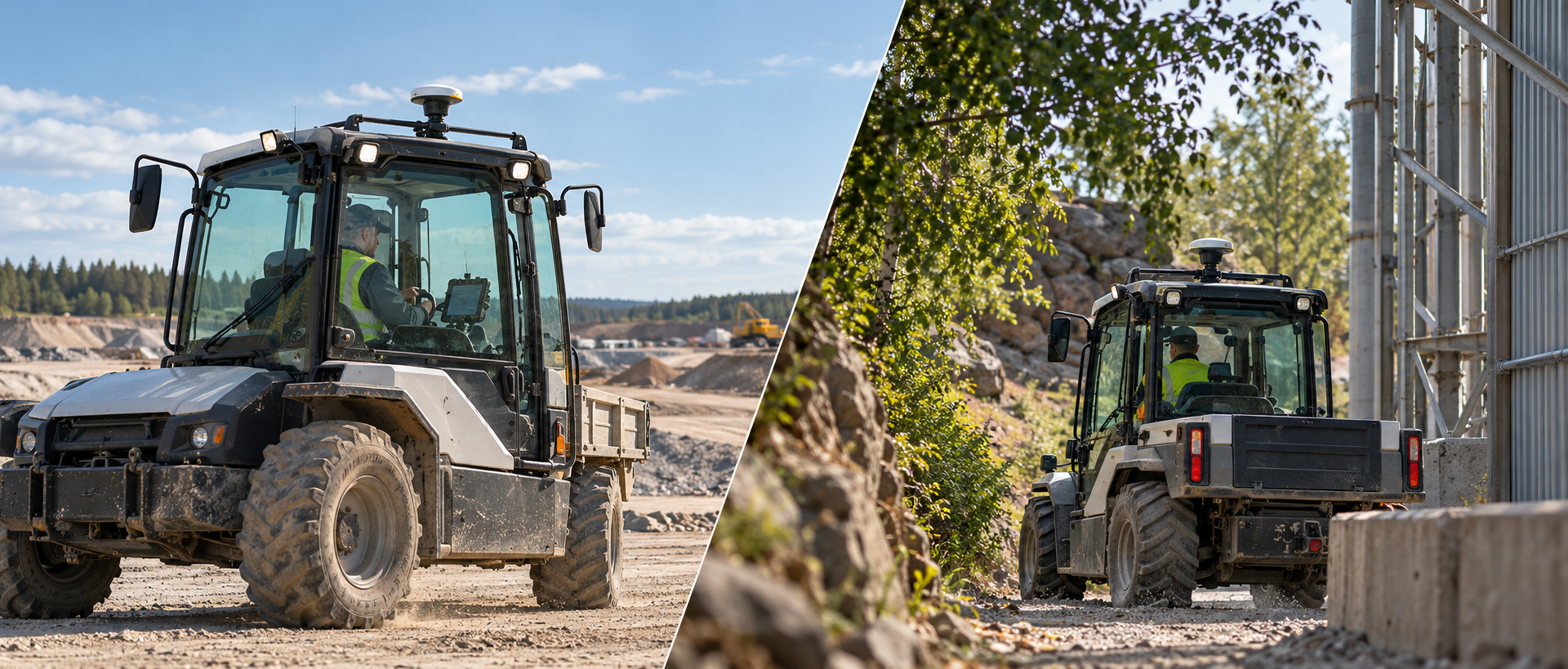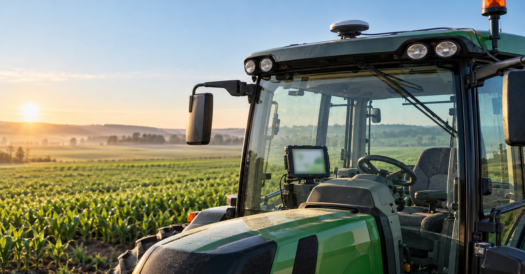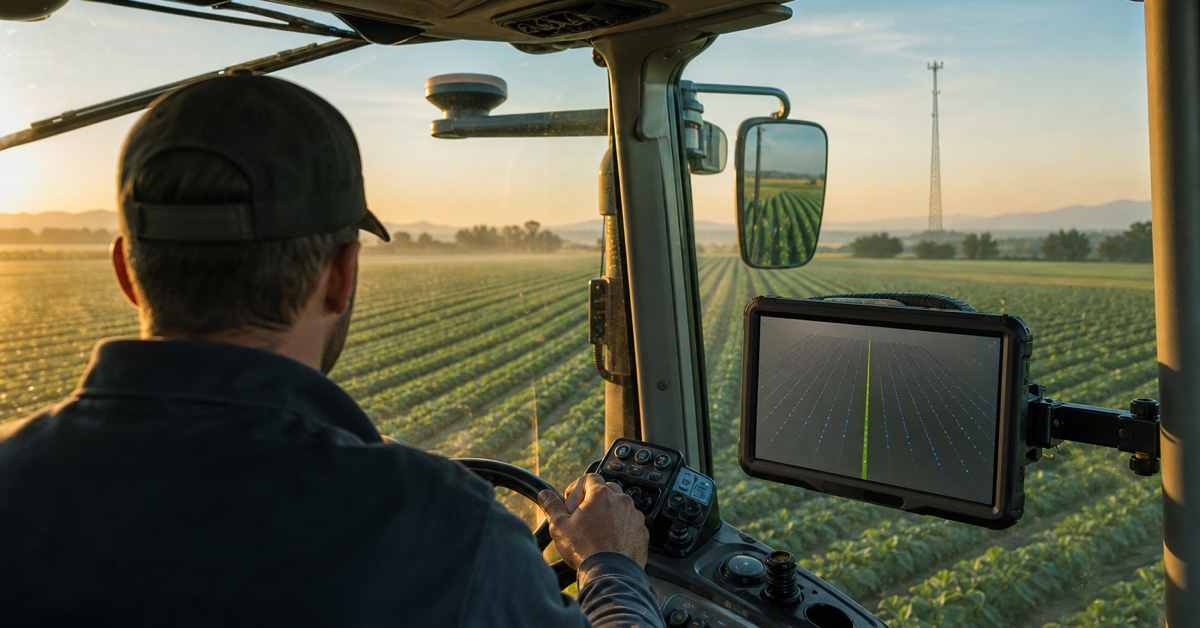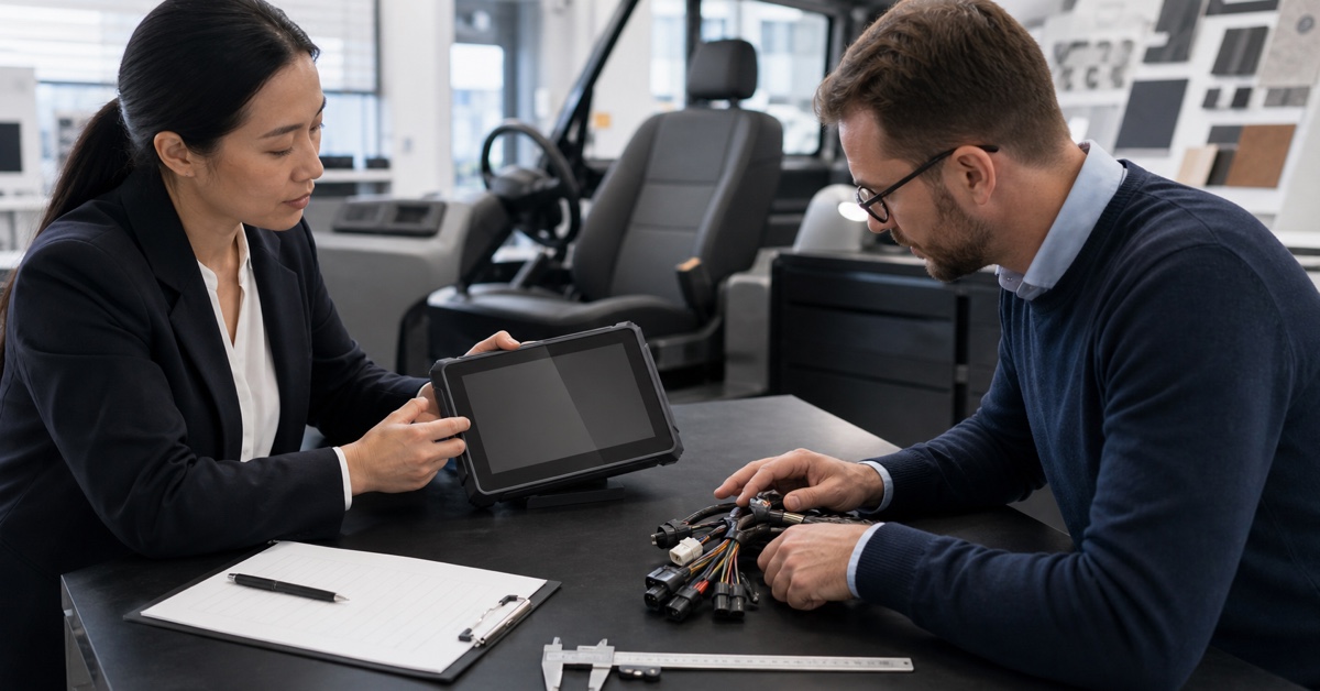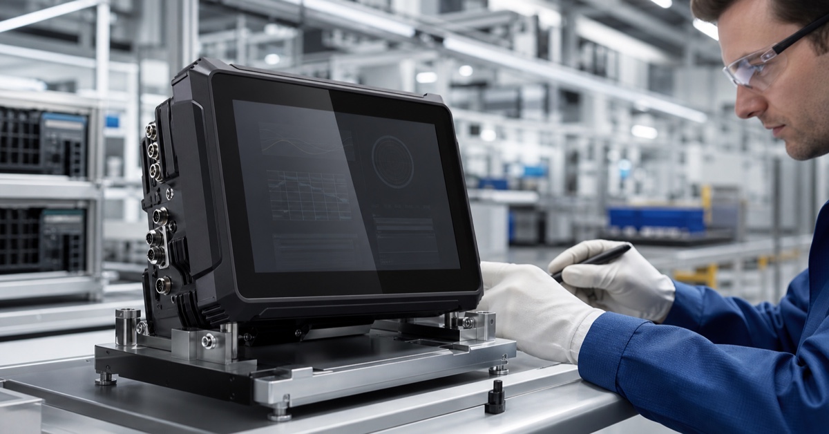

A vehicle terminal for loaders sits at the center of a fast, repetitive job. The machine travels between a pile and a truck, changes direction frequently, works close to people and other equipment, and often operates in dust that quickly covers windows and cameras. The operator needs useful information without losing attention on the bucket and travel path.
For that reason, loader terminals are usually most successful when they do a few jobs very well: show the right camera, present clear machine or dispatch information, record work consistently, continue through coverage gaps, and recover after every engine start. This guide explains the requirements behind those outcomes and where PDS terminals fit.
1. Industry challenges in loader operations
Loaders combine vibration with frequent acceleration, braking, steering, and direction changes. The terminal, bracket, and harness experience repeated movement throughout the shift. A display that shakes at idle or a cable that pulls against the connector will become a daily nuisance before it becomes a hardware failure.
The work area also changes constantly. A reversing route that was clear a minute ago may now contain a truck, a worker, or another loader. Cameras can improve visibility, but only when the lens is placed correctly, the image appears quickly, and the operator can understand which direction is shown.
Dust and glare reduce usable visibility. Fine material settles on the screen, camera lens, connectors, and ventilation paths. Bright outdoor light may enter from several angles as the machine turns. The HMI needs large touch targets, restrained information density, and a display position that avoids strong reflections where possible.
2. Device requirements for loaders
A compact, stable installation
Loader cabs often leave limited space between the windscreen, controls, mirrors, and existing instruments. An 8-inch terminal is a practical starting point because it can present a focused application without dominating the cab. The bracket should hold the display steady on rough ground and allow adjustment without loosening during use.
Place a cardboard or printed mock-up in the cab before ordering brackets. Check the bucket and travel sight lines, operator reach, cable bends, seat movement, door clearance, and service access. Repeat the check with the display tilted for day and night operation.
Dust, temperature, and vibration protection
A construction machinery vehicle terminal needs protection that applies to the full installation. PDS T8Pro lists IP66, -20°C to +70°C operation, MIL-STD-810 vibration, and ISO 16750 impact references. Confirm the relevant test conditions, quoted connector set, and harness before treating those figures as acceptance evidence.
Sealing also depends on cable routing and unused connectors. Keep mated connectors away from standing water and direct mechanical damage. Support the harness close to the computer, then provide enough slack for bracket adjustment. A clean installation is easier to inspect and less likely to be disturbed during maintenance.
Vehicle power and ignition behavior
Loaders are stopped and restarted during breaks, refueling, shift changes, and maintenance. The terminal should start predictably, restore the correct machine profile, and protect open records at shutdown. PDS T8Pro specifies 9–36V DC input, but the system designer must still define B+, ACC, ground, fuse, transient limits, standby current, and controlled shutdown timing.
3. Recommended features for a loader terminal
CAN data for machine status
CAN can connect the terminal to the loader's available machine data, provided the OEM or project owner supplies the correct message definitions and permissions. Common project needs include engine hours, operating state, warnings, speed, fuel-related data, or service information. Do not assume that the same CAN database works across different loader models.
Define what the application does when a message becomes stale or the bus disconnects. A frozen value that still looks current is worse than a clear “data unavailable” state. Log connection quality and recovery so technicians can separate a vehicle-data problem from an application problem.
Camera views for travel and loading
Start with a blind-spot walk-around. Mark rear, side, bucket, and hitch areas that are difficult to see from the seat. A rear view may need to appear when reverse is selected; a side view may be more useful near trucks or stockpile edges. The application should change views consistently and avoid covering a critical alarm.
Check camera field of view, low-light behavior, dust buildup, mounting protection, connector sealing, cable length, and video format. T8Pro offers configurable I/O combinations that can include four camera inputs, dual CAN, and serial or GPIO interfaces. Match the ordered combination to the camera plan rather than assuming every unit has every port.
Dispatch and offline work
A loader may receive truck assignments, material types, target locations, or shift messages from a site system. When coverage is weak, the current task should remain available. Store essential assignments locally, timestamp status updates, and queue outgoing records until the connection returns.
Retry logic needs testing. Switch the network off during a task, create several updates, then restore it. Confirm that all records arrive once, in order, with their original timestamps. This test is simple and often reveals more than a connectivity speed measurement.
GNSS, geofencing, and optional RTK
Standard GNSS can support machine location, route history, and broad geofencing. Higher-precision RTK may be relevant for specialized stockpile measurement, guidance, or automation projects, but it should not be added without a defined accuracy and correction plan. Antenna placement, sky view, multipath, correction delivery, and loss-of-fix behavior all affect the result.
4. PDS terminal options for loader projects
| Loader application | PDS model to review | Relevant starting point |
|---|---|---|
| Compact HMI, cameras, CAN, and dispatch | T8Pro | 8-inch display, Android 11/13, configurable camera/CAN/serial/GPIO I/O, GNSS, optional RTK, IP66 |
| Focused telematics or single-camera application | T8 | 8-inch display, Android 10, GNSS, CAN, RS485, Ethernet, camera input, 9–36V, IP66 |
| Larger multi-view screen or richer application | T10Pro | 10.1-inch display, four cameras, dual CAN, RS232, optional RTK and radio, IP66 |
For most loader-cab layouts, T8Pro is the first model to evaluate because of its compact display and configurable interfaces. T10Pro becomes attractive when the application needs more screen area for several views or complex machine information. T8 can fit projects with a narrower functional scope.
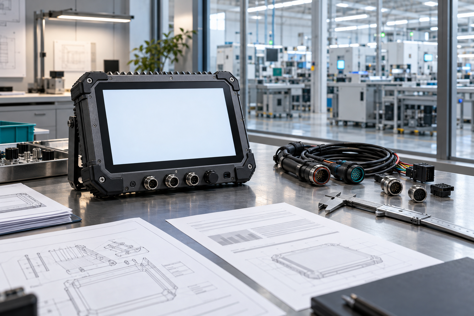
Model selection is only the start. Confirm memory, storage, OS version, modem region, GNSS or RTK option, exact I/O combination, camera standard, pinout, harness, and bracket in the order. An OEM vehicle terminal for loaders should have a controlled configuration record that the supplier and buyer can both inspect.
5. Application example: material movement at a stockyard
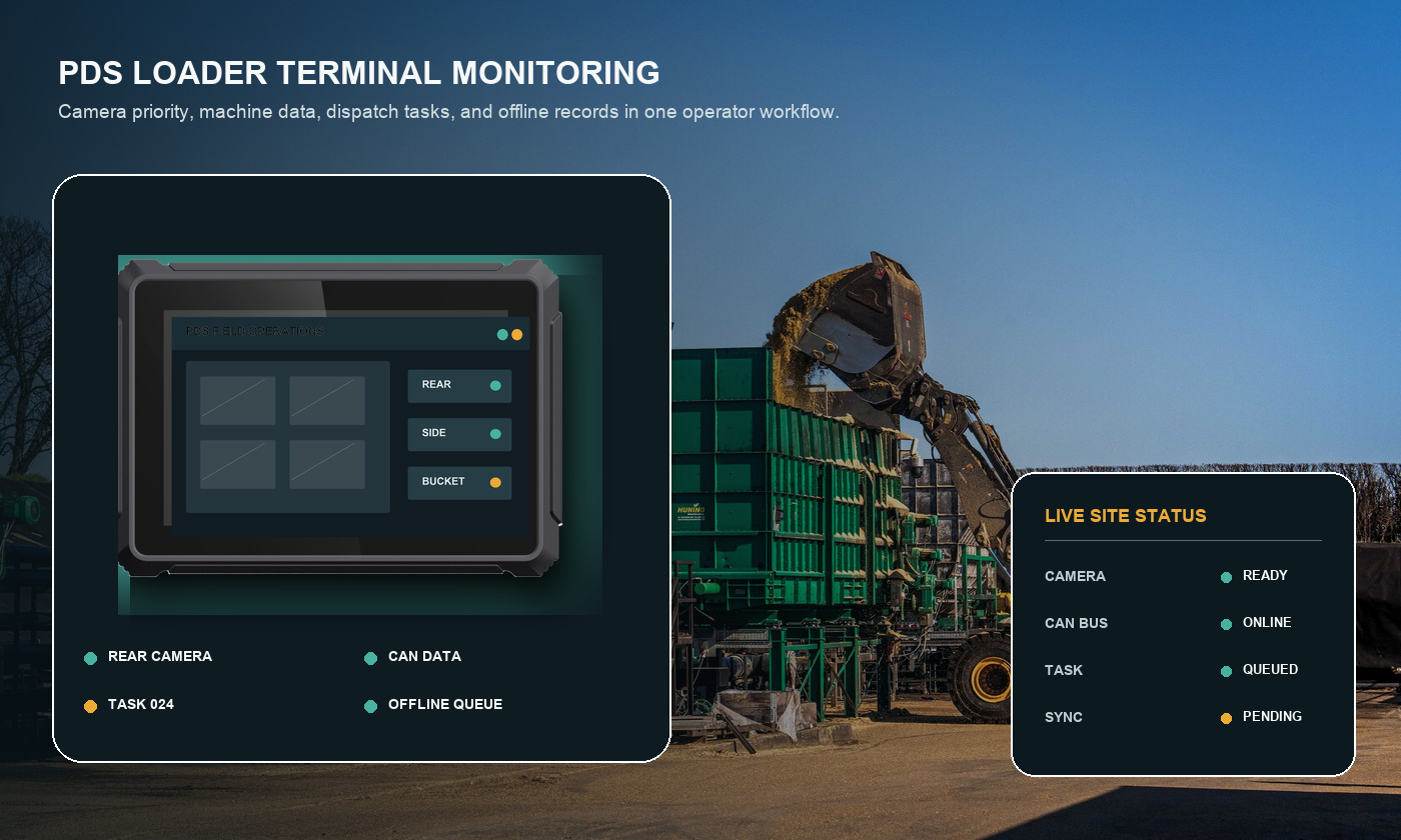
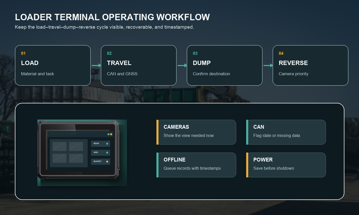
A loader begins the shift by identifying the operator and machine. The terminal downloads the current material assignments and keeps a local copy. During travel, it shows a simple task screen and machine warnings. When reverse is selected, the rear camera takes priority. At the loading point, the operator confirms the material and destination with one or two large controls.
Network coverage becomes weak behind a stockpile. The application continues using the current assignment and stores completed movements locally. When the loader returns to coverage, the terminal uploads the queued records with their original times. A supervisor can then review the shift without gaps or duplicated trips.
At key-off, the terminal saves the last task state, connection status, and pending queue before power is removed. The next operator receives the correct machine profile rather than an abandoned screen from the previous shift.
6. Pilot checklist for loader installations
- Confirm that the terminal and bracket do not block the bucket, travel path, mirrors, or cab exit.
- Run the real application with cameras, CAN data, GNSS, local logging, and wireless synchronization active together.
- Check the display in direct sun, cab shade, dusty conditions, and at night.
- Drive over representative rough ground and inspect the bracket, harness, and connectors afterward.
- Test cranking, rapid key cycles, low-voltage behavior, and controlled shutdown.
- Disconnect one camera and the CAN bus; verify clear warnings and automatic recovery.
- Remove network coverage during several work records, then verify one-time ordered upload.
- Freeze the hardware BOM, OS image, application, harness, bracket, and acceptance limits before rollout.
Frequently asked questions
Is an 8-inch terminal large enough for a loader?
Often, yes. It works well for focused dispatch, machine data, and camera screens in a compact cab. Use a 10.1-inch terminal when the application needs more simultaneous information. Test both sizes with the real layout.
How many cameras should a loader terminal support?
There is no universal number. Map the actual blind spots and movements first. Rear, side, bucket, or hitch views may each be useful, but the application must present them at the right time and report failures clearly.
Can one configuration cover loaders from different manufacturers?
The terminal platform may be shared, but brackets, harnesses, CAN databases, power wiring, and software profiles often differ. Keep those vehicle-specific items under configuration control and validate each representative model.
Make the terminal part of the loader workflow
A well-specified vehicle terminal for loaders stays out of the operator's way while making the work easier to see, record, and support. Start with the load–travel–dump–reverse cycle, choose interfaces that match the machine, and prove the complete installation before fleet rollout.
See the PDS construction and mining solution, review the PDS 8-inch terminal range, or contact PDS Technology with your loader models, camera plan, vehicle data, software, and installation constraints.
Contact us
📧Email:[email protected]
📞Tel:+86 13421822024
🌐Website: www.szpds.com
Disclaimer
The information in this article is for reference only. PDS Technology Co., Ltd. assumes no responsibility for errors, omissions, or suitability of the content for specific applications. Product specifications are subject to change without notice. Buyers should verify all technical details with our team before use.
About PDS Technology
PDS Technology is a leading OEM/ODM manufacturer of high-precision RTK GNSS terminals and vehicle computers, serving agriculture, construction, mining, taxi, and logistics industries since 2011.
With 15+ years of automotive-grade R&D experience, we offer rugged, multi-OS (Android/Linux/OpenHarmony) devices featuring RTK centimeter-level positioning, IP66 protection, and AI-ready performance. Our IATF16949-certified factories have produced over 100,000 units deployed globally, holding 30%+ of China's agricultural auto-steering terminal market. We export to Japan, the US, UK, Turkey, Russia, and beyond.