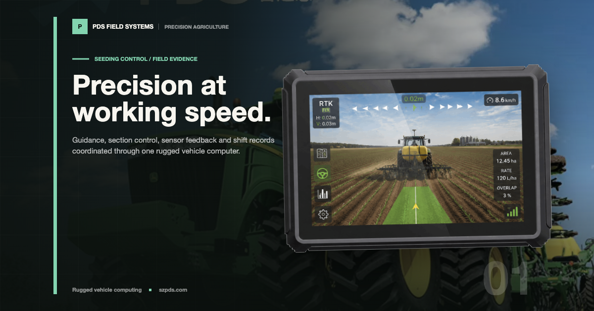

A missed-seed percentage can look exact while the driver is still asking the useful question: what should happen next? Which row changed? Was that section supposed to be running? Did the sensor go quiet, or did the application discard the pulse? A useful seeding monitor answers those questions before it adds another decimal place.
My test for the screen is simple: could a driver make the next safe decision without calling the engineer? The same display should leave enough evidence for that engineer to reconstruct the event later. Treat every irregular pulse as an emergency and the driver stops trusting the screen. Treat a disconnected sensor as a healthy row and the screen gives false confidence.
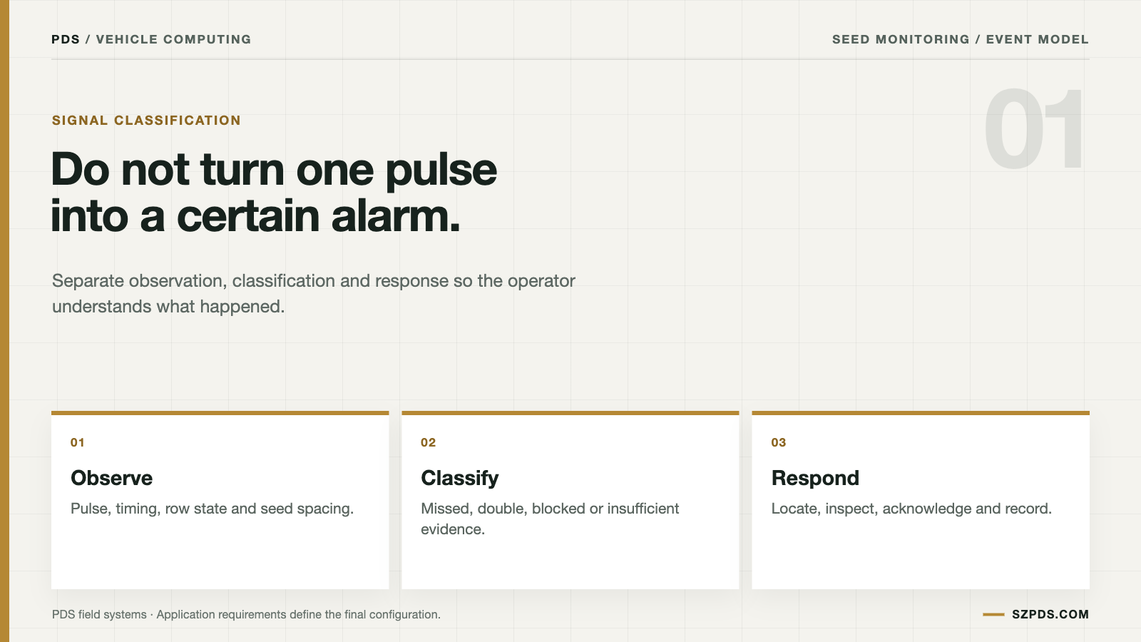
Before comparing screen sizes, write down the event model. The sensor produces a signal. The application interprets it against timing and machine state. The driver sees a classification and chooses an action. If those steps are compressed into one vague "alarm" feature, the result is difficult to test after a bad pass. The wording matters because each step has a different owner.
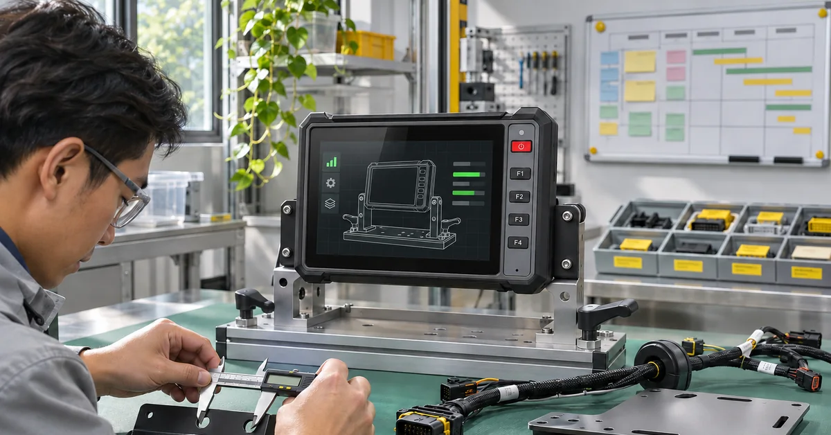
Product review still needs numbers. PDS lists models with different display sizes, camera capacity and vehicle interfaces. The published T12 specification, for example, describes up to four 1080P camera previews and two CAN networks. Those figures can narrow a shortlist. They do not establish a row-count limit for a monitoring application. That workload belongs in a test on the intended build.
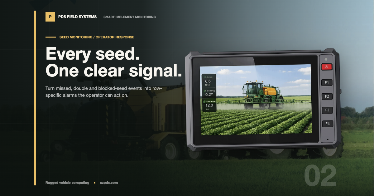
A seeding monitor display is useful only when the operator can distinguish a missed seed from a double seed and confirm the affected row. Pair each seeding monitor display alarm with the commanded rate, sensor state, and recovery action, then review that record at shift end.
Start with the missed-seed rule, not the alarm color
A seed sensor may produce one pulse for one seed, but the monitor never observes "seed" in the abstract. It decides whether an expected event arrived while the row was commanded on and the machine was in a state where measurement made sense. No valid pulse inside the window could mean a missed seed, a blocked path or a measurement problem. The screen should not pretend those causes are identical.
The window depends on target population, ground speed, row spacing, sensor behavior and section state. A timeout that looks harmless on a straight pass may chatter during a slow turn. At working speed, it may arrive too late to help before the next inspection opportunity. The number means something only in that operating context.
Someone who did not design the screen should still be able to explain the rule. For example, row 7 is flagged only after the section is commanded on, the start-up window has passed and no valid pulse arrives inside the calculated interval. "Show missed seed" is a label. It becomes an acceptance criterion when the timing and machine-state conditions are written down. Ask a second operator to repeat the explanation before calling the rule clear.
Speed loss and target loss need their own behavior. The monitor might pause classification, hold the last known state or mark the row unobserved. Each choice can be defensible. A guessed classification that still looks like a crop result after measurement has disappeared is much harder to defend.
Do not call every close pulse a double
Two close pulses may represent two seeds. They may also be a split signal, vibration, dust or one seed seen twice by the sensing arrangement. The classification window belongs to the selected sensor and operating range. A convenient value in a screen mock-up is not a substitute for that boundary.
Population and spacing are easy to mix up. A row can produce the expected average count while placing seeds unevenly. Use a singulation claim only when the sensor and algorithm measure the timing behind it. An average count cannot carry that meaning by itself.
When confidence is low, show the uncertainty. A suspected double and a confirmed blockage lead to different inspections. Give them the same visual treatment and the driver is sent toward the wrong check. The display can be useful without guessing the mechanical cause.
Use alarm states that match the job
| Observed condition | What may be happening | Useful display state |
|---|---|---|
| One isolated irregular pulse | Noise or normal variation | Keep a row note; do not interrupt the job without a defined reason |
| Repeated missed pulses on one row | Blockage, empty meter, sensor fault or poor flow | Row alarm with duration and a short inspection action |
| Similar events on several rows | Shared drive, material, rate or network issue | System-level warning that points to common causes |
| Sensor signal lost | Detection is unavailable | Unobserved row, not a healthy zero-seed result |
| Section intentionally off | No seed flow is expected | Show section state and suppress the normal-flow alarm |
Unobserved is a real state, not a cosmetic label. Calling a disconnected sensor healthy gives the driver confidence at the exact moment measurement has stopped. That is the moment for an explicit message, not a quiet green row.
Give the cab and the service team different views
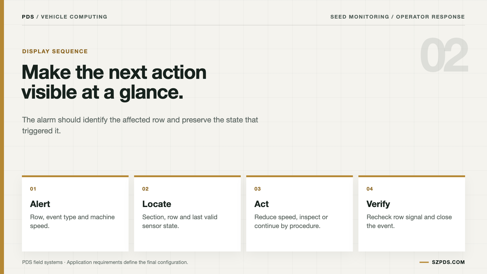
During a pass, the driver needs row identity, event type, current rate and a next action. "Stop and inspect", "continue to the headland" and "use the approved fallback" are different instructions. A generic warning leaves the driver to interpret the system while managing the machine. A product decision should not be hidden there.
During diagnosis, the team may need raw or processed pulses, timestamps, position, target, actual value, section state, software build and sensor identifier. Put that material in a diagnostic view or job export. It belongs there. On a driving screen, especially in daylight, it becomes distraction.
A driver should not have to interpret a diagnostic trace in daylight. An engineer should not have to reconstruct the event from one screenshot after the machine stopped. Share the data, not necessarily all of it on one screen.
Watch the transition at the headland
The useful test begins before movement. Select the field, confirm the implement, set the target and show the driver how a missing sensor will appear. Repeat the sequence at working speed with vibration, glare and gloves included. A clean lab display tells little about the warning in the cab.
Headland transitions expose weak rules quickly. An alarm that continues after a section is commanded off creates noise. One that appears during every normal transition teaches operators to ignore the display. The classifier may be consistent, but the workflow is still failing.
End the trial with a planned restart. The display should recover the correct job, identify the active build and show which rows still need confirmation. If a reboot clears alarm history, say so in the interface. Reaching the first screen quickly does not mean the work was recovered.
ISOBUS task and implement functions may provide a common vocabulary. It does not define what "missed" means for a particular sensor, crop or controller. That event model remains a project decision and should be tested on the intended combination.
Use controlled pulses to find the boundaries
The bench does not need to reproduce the whole planter. Keep the intended controller, vehicle computer and application in the loop. Use an approved service tool to create known input patterns. The experiment stays repeatable without pretending that a pulse generator is a working implement.
Start with a regular train of pulses. Increase the gap one step at a time and note where the row changes from normal to missed. Reverse the exercise with closely spaced pulses and record the double-seed boundary. Keep the row, sensor and software identifiers beside the results. A threshold without its build may belong to somebody else's test.
After the clean cases, add a short noise burst, remove the sensor for a defined period and switch the section off. Repeat each pattern on the planned build. The useful record shows the input pattern, row, operating state and displayed result. A single pass percentage cannot explain an alarm that a field technician cannot reproduce.
Keep an alarm open long enough to be useful
The first red pixel is not the end of the event. The operator may mark a location, inspect the row, refill material, reseat a connector or continue under a downtime procedure. Preserve enough context for later inspection: row, position, section command, sensor state and action taken.
For jobs that need history, open, inspected, temporary fallback and closed are more useful states than one red-to-green transition. Clearing an alarm after one good pulse can hide an intermittent fault. Requiring acknowledgement for every brief event creates a different kind of fatigue. Choose the rule according to what the operator loses when the condition goes unnoticed.
Choose the terminal around the complete workload
| Requirement | Question to answer | Evidence |
|---|---|---|
| Visibility | Can row identity and next action be read in the intended cab? | Viewing test with gloves, vibration and daylight |
| Interfaces | Which CAN, serial, Ethernet or USB paths carry the events? | Drawing, driver scope and reconnect result |
| Processing | Can the build handle the required rows, events and logging? | Measured workload with the target application |
| Storage | How long does useful event evidence remain available? | Retention, export and offline test |
| Power | What happens during crank, shutdown and interruption? | Approved vehicle-sequence result |
| Service | Can another technician restore the row configuration? | Recovery record and spare-unit procedure |
A larger display can show more information and still be a worse monitor if the alarm hierarchy becomes crowded. Review the smallest screen and tightest installation the project must support. Then test the layout with the person who will drive. The largest unit is only one part of the decision.
For a shortlist, review the PDS precision agriculture solution, the precision agriculture vehicle computer guide and the 10-inch vehicle computer.
Make the report useful after connectivity fails
A support report has five plain questions to answer: which row changed, when and where, what was commanded, what feedback arrived, and which build and sensor were present. Without those answers, it is a display capture rather than an incident record. A polished screenshot cannot supply missing timestamps.
Keep the raw event export separate from the short alarm history. A farm manager may need a short list of rows and locations. An engineer investigating the same row a week later may need the complete pulse sequence. Both records matter. One crowded view serves neither person well.
Connectivity loss needs an explicit policy. If the network disappears, does the terminal retain events, queue them, warn the driver or stop the job? When queued records are sent later, the system also needs duplicate prevention and a way to show that delayed data is no longer live. Otherwise an old event can look current.
Specify the monitor before comparing products
Before comparing products, write down the rows, sensors, event definitions, priority levels, recovery actions and exports. A supplier can quote against that list and show what was tested. "Smart monitor" may work in a brochure. It is not a testable specification.
Without that scope, a comparison can reward a polished screen that has never met the selected sensor, crop range or software build. The display is part of the system. It cannot compensate for a weak sensing or control path behind it.
FAQ
Can one display show missed and double seeds?
Yes, when the sensor data and application can distinguish the relevant timing patterns. Test the limits for the selected crop, rate, sensor and software build. Do not assume one threshold will work across every implement.
Is a population percentage enough?
No. It can hide a one-row fault and says little about spacing, timing or whether the sensor was available for the whole pass.
Should every pulse interval be shown to the operator?
Usually not. Keep detailed evidence for diagnosis and make the driving view about stable states that lead to an action. A pulse trace can help an engineer while distracting a driver at the wrong moment.
What should happen when a sensor disconnects?
Mark the row unobserved, show the fault and state the approved fallback. Do not present loss of measurement as a normal zero-seed result.
Can the display identify the mechanical cause automatically?
It can narrow the investigation with row, timing and operating state. Physical inspection remains necessary for seed, meter, harness and sensor causes. The display can point to where to look, but its inputs may not support certainty about the cause.
How many rows can one terminal support?
It depends on the interfaces, event rate, application design, logging and tested build. Ask for a measured result with the actual row count and workload. Screen size alone is not the processing limit.
Does an ISOBUS-compatible display guarantee a working monitor?
No. Confirm the exact functions, messages, profiles, timing and validation scope required by the selected implement. A compatibility label starts the test; it is not the result.
Should alarms clear automatically?
Only when the return to a good state is stable and safe for the job. Otherwise use acknowledgement or a defined hold period. One good pulse must not hide an intermittent fault.
What belongs on the main screen?
Prioritize row state, event identity, commanded rate and next action. Put detailed traces in a diagnostic view or export. They support diagnosis without crowding the driving task.
What is the first pilot test?
Inject controlled pulse patterns and verify classification, row identity, alarm behavior, logging, restart recovery and the operator action on the planned build. Repeat one fault case while the network is unavailable. That last step often exposes whether the report is really usable.
Field acceptance checklist
Turn the display claim into a repeatable acceptance check before the machine enters a field trial. The reviewer should be able to identify the row, reproduce the input, see the classification, choose the operator action and retrieve the event after a restart. That sequence is more useful than a screenshot of a green dashboard.
- Define the sensor input, row identity, timing window and machine state for missed, double and blocked-seed events.
- Test normal pulses, long gaps, close pulses, sensor disconnects and section-off states with known inputs.
- Record alarm priority, wording, acknowledgement, persistence and the safe action expected from the driver.
- Verify that the terminal retains the event, software build, row and correction state after connectivity loss or restart.
- Repeat one case at the headland and one case on the intended vehicle build before approving the monitor.
Conclusion
Missed and double seed monitoring joins sensing, classification and operator action. A useful seeding monitor display makes that chain legible without pretending that one percentage explains a whole row.
Write the event rule so another engineer can test it. Challenge it with known inputs and keep the result beside its build. The driver gets a calmer workflow. The engineering team gets something better than a screenshot when the machine leaves the test bay.
Contact us
Email: [email protected]
Tel: +86 13421822024
Website: www.szpds.com
About PDS Technology | Contact PDS Technology | Privacy and terms inquiries
Disclaimer
The information in this article is for reference only. PDS Technology Co., Ltd. assumes no responsibility for errors, omissions, or suitability of the content for specific applications. Product specifications are subject to change without notice. Buyers should verify all technical details with our team before use.
About PDS Technology
PDS Technology is a leading OEM/ODM manufacturer of high-precision RTK GNSS terminals and vehicle computers, serving agriculture, construction, mining, taxi, and logistics markets since 2011.
With 15+ years of automotive-grade R&D experience, we offer rugged, multi-OS (Android/Linux/OpenHarmony) devices featuring RTK centimeter-level positioning, IP66 protection, and AI-ready performance. Our IATF16949-certified factories have produced over 100,000 units deployed globally, holding 30%+ of China's agricultural auto-steering terminal market. We export to Japan, the US, UK, Turkey, Russia, and beyond.