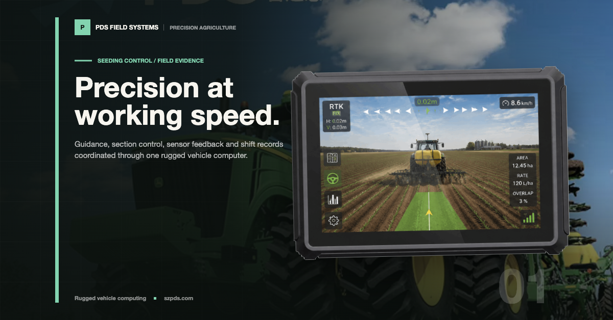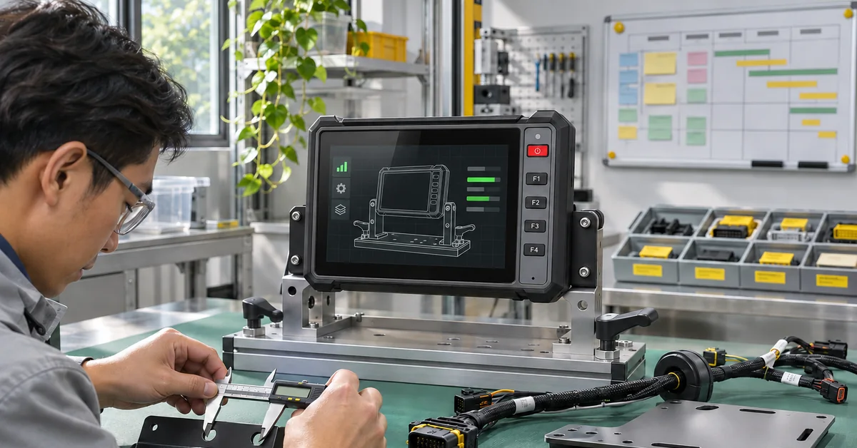

Picture a driver watching row 7 stop planting halfway through a pass. The rate on the terminal has not necessarily changed with it. Maybe the prescription was edited. Maybe the section controller rejected a command. Maybe the meter is still turning even though the sensor has gone quiet. From the cab, those cases look alike. At the harness and application level, they are separate faults.
When I review a precision seeding system, I start with those questions rather than the display diagonal. What was requested? Which device accepted it? What part actually moved? Which signal proves that it moved? A larger panel can make a map easier to read. It cannot close the control loop or prove that seed flow changed.
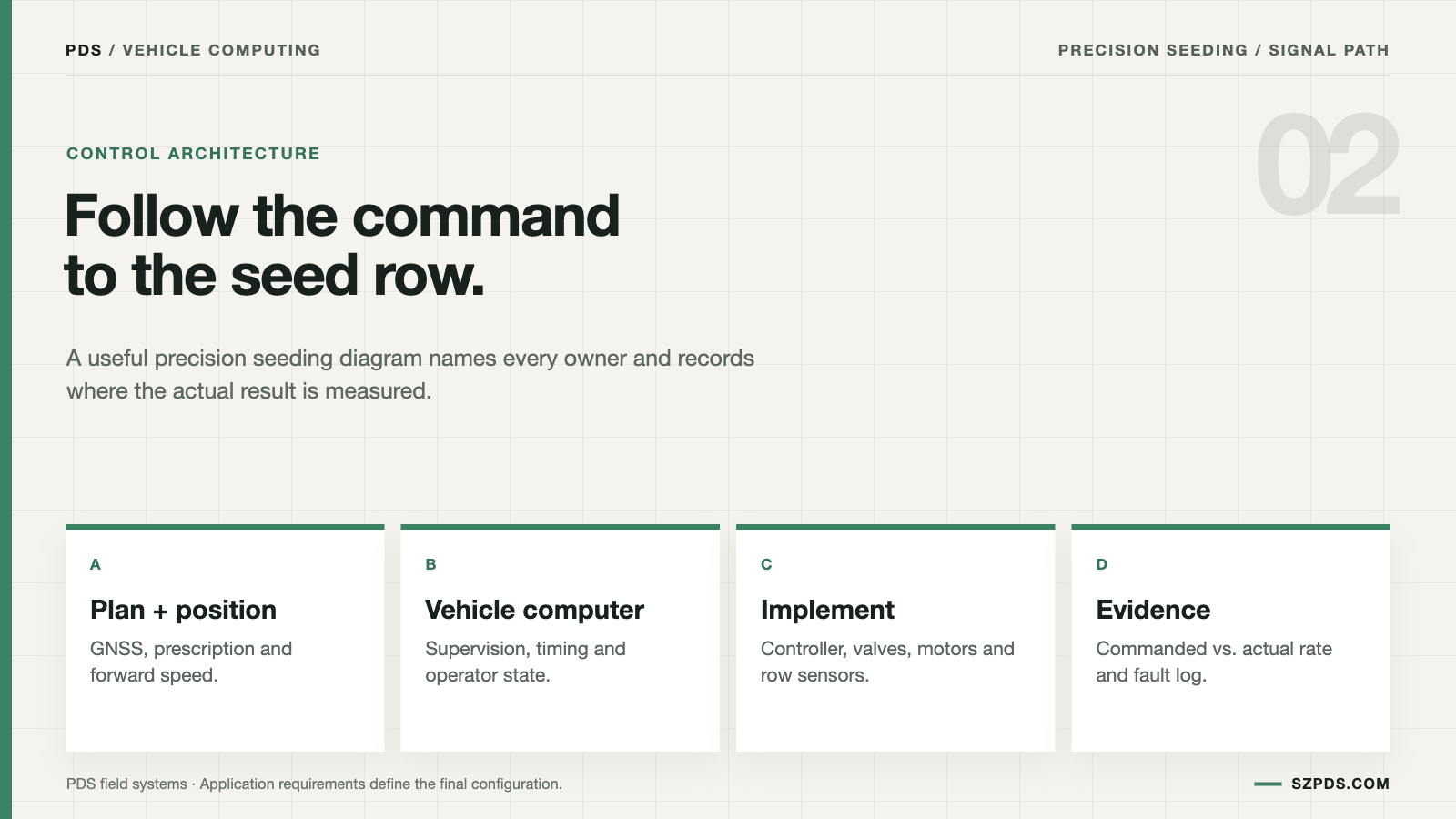
At an OEM review, I ask a less glamorous question before discussing screen size: who is allowed to make each decision? The vehicle computer may manage the job, networks, records and operator commands. A sensor observes an event. A dedicated controller may close the fast loop. The row unit performs the mechanical work. If one product combines two or more of those roles, write the arrangement into the quotation. Do not leave it in a demo engineer's head.
For a PDS shortlist, I would treat a T7, a T10-class unit and a T12 as workload candidates, not ready-made system answers. Screen area is only one filter. CAN, serial, Ethernet, video load, storage and the intended software image matter just as much. The compatibility claim starts after the application has run with the implement and harness that will actually be used.
Draw the command path before choosing the screen
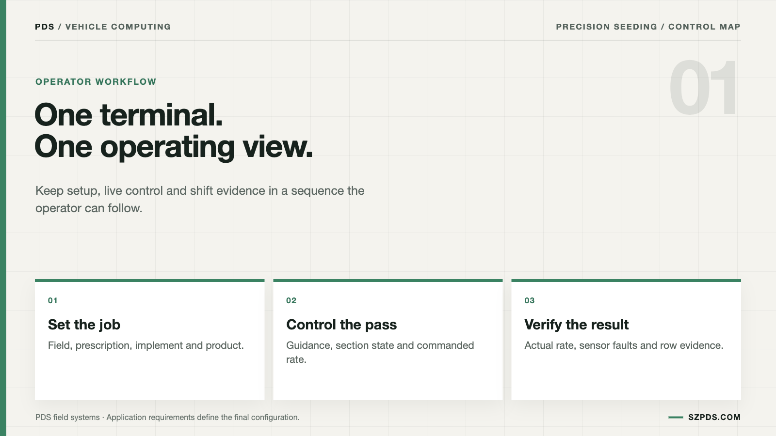
Use an ordinary rate change as the first worksheet exercise. A flashy demonstration can hide ownership; a routine change exposes it. Follow the target from its source to the receiving device. Then write down which physical part should move and which signal will confirm that it moved. The path may pass through a prescription map, task controller, drive motor, seed sensor, section valve and several networks. It becomes manageable when every arrow has an owner.
Label each arrow with its real interface: CAN, Ethernet, serial, pulse, analog or an application API. "Data connection" will not help a technician beside a headland. Add timing limits in the workshop. A missing number is easy to debate there and expensive to discover with soil on the machine.
Give the return path the same attention as the outbound command. A terminal may display the target rate while receiving no measured seed feedback. That arrangement can be valid for an open-loop job. It should be named accurately in the acceptance test, because a displayed target is not evidence of closed-loop control.
The first workshop can be deliberately plain: straight pass, turn, section change, then stop. At each point, capture the target, command, physical response, feedback and message shown to the driver. Those five entries make the display one design choice among several. They stop it becoming a proxy for the whole machine.
Give the vehicle computer the work it can actually own
Job setup and operator decisions
The terminal is often where the driver selects the field, loads a prescription, chooses a product and confirms the implement. Those actions create the job state. When a support engineer opens the record later, the field, product, implement profile and software build should be there. The engineer should not need an interview about what happened before sunrise.
Put the awkward questions on the first review sheet. What does pause mean when the implement connects late? Can the driver resume after a turn? Does a green section icon mean a command, a confirmed state or only the last value received? Get those answers before the field trial. A smooth demonstration can blur all three states.
Network and peripheral coordination
A precision seeding vehicle computer may sit between tractor CAN, implement CAN, GNSS, cameras and a remote service. Connector count is only the beginning. The integration record needs to show which messages cross each boundary. It also needs an owner for translation, timeout, retry and fault logging when one side stops answering.
For each gateway, name the source, destination, update behavior and degraded state. A connector may remain electrically live after the application has lost permission to use it. A voltage reading proves that the socket is powered. It does not show that the job can use the interface or that the application will recover it.
Records that can be used later
Keep the job identifier beside the software build, GNSS time, target rate, actual value, section state and fault transitions. Keeping every raw signal forever may be unnecessary. Keeping enough context to identify the build and explain the event is part of the service design, not an optional reporting feature.
A screenshot may help during a meeting and still be weak evidence. The follow-up questions arrive quickly: was the number commanded or measured, which implement profile was loaded, and did the warning survive a restart? Put those answers in the record. Reconstructing them from memory is a poor service process.
Guidance and task control are related, not identical
Guidance and seeding can share one terminal without becoming one claim. Guidance accuracy describes position. A section command describes an instruction. Neither measurement proves seed placement or a physical stop in seed flow. The interface may show both, but the test plan should keep the evidence separate.
Test the two claims separately before combining them. Headlands, slow turns and a short network interruption are useful because timing errors often appear while the screen still looks convincing. A straight pass is the easy case. The field review also needs setup, turning, fault handling and recovery.
Keep measurement and fast control close to the implement
| Function | Likely owner | Evidence to request |
|---|---|---|
| Seed event detection | Sensor and signal-conditioning hardware | Placement, signal definition, blockage behavior and false-trigger limits |
| Rate or valve loop | Dedicated controller or implement module | Timing, safe state and response when feedback disappears |
| Row shutoff | Section controller, clutch or valve | Command delay and confirmation of physical state |
| Population and spacing | Meter, drive and row unit | Metering test, seed range and mechanical limits |
| Guidance position | GNSS receiver and correction source | Correction status, mounting and loss-of-signal behavior |
| Operator workflow and records | Vehicle computer and application | Job record, alarms, build identity and recovery path |
This table is a review aid, not a universal wiring diagram. One project may combine functions; another may divide them between the terminal, implement module and row electronics. For each row, ask the practical question: which device performs the physical work, and which device is only reporting a state?
ISOBUS and task-control concepts give teams a common vocabulary. They do not demonstrate that a particular implement profile, prescription or optional function works on the selected build. That part still belongs in the test plan, with the actual software and implement connected.
Define section control by evidence, not by icons
Before the trial, define what "closed" means for this machine. A changed icon, controller acknowledgement, valve or clutch movement and stopped seed flow are four different observations. They can disagree. The acceptance record should name the decisive proof and retain the supporting signals beside it.
Measure command time and physical response time. Repeat the check at low speed and through an angled headland. Then remove the implement network or restart the terminal. Record what the machine does, not just what the display does. The difference between those records is often the point of the acceptance test.
Choose the fallback before the trial. Holding the last rate, stopping or asking for confirmation may each be reasonable for a different machine. What is difficult to defend is a policy invented by the operator while the machine is moving.
Use known inputs for missed and double events
A field run can show that an alarm occurred, but it is an expensive place to discover the boundary of the rule. Start on a bench with a simulator or approved service tool. Generate a regular pulse train, a long gap, closely spaced pulses and a short noise burst. Keep the input patterns with the build record so somebody else can repeat the result.
The note should include target rate, assumed ground speed, row number, sensor identity and software build. Increase the gap until the display changes to missed. Then repeat with the section intentionally off. If the same alarm appears when no seed flow is expected, inspect the state model before blaming the seed path.
Keep population and spacing separate in a double-event test. A row can produce the expected average count while placing seeds unevenly. Reserve the word singulation for a sensor and algorithm that measure the relevant timing; an average percentage cannot carry that claim by itself.
Write the boundary into the RFQ
| Question | Vehicle computer scope | Customer or implement scope |
|---|---|---|
| Who supplies the application? | Platform and agreed integration support | Prescription, agronomic workflow and customer UI |
| Who defines sensor messages? | Transport, logging and display support where included | Sensor and implement controller owners |
| Who validates seed population? | Command and record verification | Metering, seed condition and row-unit performance |
| Who approves section behavior? | Display and command checks | Implement configuration and field acceptance |
| Who handles field recovery? | Terminal, connectivity and software route | Harness, sensor, implement and tractor service |
Keep the matrix beside the interface list. If row 7 is missed, the next person should know whether to inspect the sensor, controller, harness, application or operator procedure. That turns the RFQ into a document a supplier can review. A feature list with no fault owner is much less useful.
For model-level discussion, review the PDS precision agriculture solution, the T10 precision seeding application and the available vehicle computers.
Build a field trial that can settle the question
A credible field trial is often deliberately boring: one ordinary job, a straight pass, a boundary turn and a controlled stop. Let the operator set it up without an engineer taking over. After a planned restart, hand the recovery task to somebody else. If only the designer can recover the system, the service route is not ready.
Save the target, actual feedback, section command, sensor event, operator acknowledgement and final job record separately. A later crop result may support an agronomic review. It cannot show what the control path did during the trial, so keep agronomic and system evidence separate.
The final question is not whether the screen looked finished. Can each owner show what its part did on the build that will ship? If the answer requires reconstructing the trial from memory, the compatibility claim is still early.
FAQ
Is a precision seeding vehicle computer the same as a planter monitor?
Not necessarily. The terminal may host monitoring, guidance, task workflow and records while another device handles timing-sensitive implement control. The wiring and software responsibilities decide the description, not the product label.
Can the terminal replace a seed controller?
Only if the architecture gives it that responsibility. In many systems, timing-sensitive actuation stays in dedicated implement hardware. Ask which device is permitted to change the physical output. A displayed value is not the same thing as control.
Does ISOBUS support guarantee implement compatibility?
No. Verify the implement profile, functions, messages, timing limits and software versions used by the project. A standards label gives the team a starting point. The connected test decides whether the selected combination works.
What proves that a section has closed?
Use the feedback named in the system design: valve, clutch, controller or seed-flow feedback, depending on the machine. A changed icon confirms a display transition only. A physical-closure claim needs evidence from the physical path.
How should a missed-seed alarm be tested?
Inject known pulse patterns and check detection, timing, row identity, display state, logging, reset behavior and the action presented to the operator. The color of the alarm is less important than whether the rule can be reproduced.
Can precision seeding work without RTK?
Some functions can use another correction mode, depending on the design. Run guidance and section tests under the correction quality the buyer will actually accept. A result achieved with the best available signal may not describe the real job.
What data should the terminal log?
At minimum, keep job and build identifiers with time, position, target, actual value, section state, alarms and the operator actions needed for later diagnosis. The support plan can decide how much raw signal data is worth retaining.
Should the terminal also control cameras?
It can, provided the model, driver, bandwidth and application support the camera workload. Scope camera recording, privacy, storage and loss-of-stream behavior beside the seeding function. Do not infer them from the presence of a video port.
Can one configuration cover several implements?
It can be designed that way. Each implement profile, connector, controller and calibration path still needs a validation result. Reusing a configuration is convenient; it is not evidence by itself.
What belongs in the first technical meeting?
Bring the command path, interface list, responsibility matrix, safe-state rules, one ordinary field job and the acceptance evidence plan. That bundle exposes open ownership before the meeting drifts into a general product presentation.
Conclusion
A precision seeding vehicle computer is easier to evaluate when its boundary is explicit. It can coordinate the operator workflow, networks and records. Sensors measure. Controllers act. The implement performs the mechanical work assigned to it. The separation gives the support team somewhere specific to start when the result on the screen disagrees with the machine.
When the value on the screen disagrees with the result in the crop, the support team can start with an owner, a signal and a build. That is more useful than arguing over a long list of interchangeable features.
Contact us
Email: [email protected]
Tel: +86 13421822024
Website: www.szpds.com
About PDS Technology | Contact PDS Technology | Privacy and terms inquiries
Disclaimer
The information in this article is for reference only. PDS Technology Co., Ltd. assumes no responsibility for errors, omissions, or suitability of the content for specific applications. Product specifications are subject to change without notice. Buyers should verify all technical details with our team before use.
About PDS Technology
PDS Technology is a leading OEM/ODM manufacturer of high-precision RTK GNSS terminals and vehicle computers, serving agriculture, construction, mining, taxi, and logistics markets since 2011.
With 15+ years of automotive-grade R&D experience, we offer rugged, multi-OS (Android/Linux/OpenHarmony) devices featuring RTK centimeter-level positioning, IP66 protection, and AI-ready performance. Our IATF16949-certified factories have produced over 100,000 units deployed globally, holding 30%+ of China's agricultural auto-steering terminal market. We export to Japan, the US, UK, Turkey, Russia, and beyond.