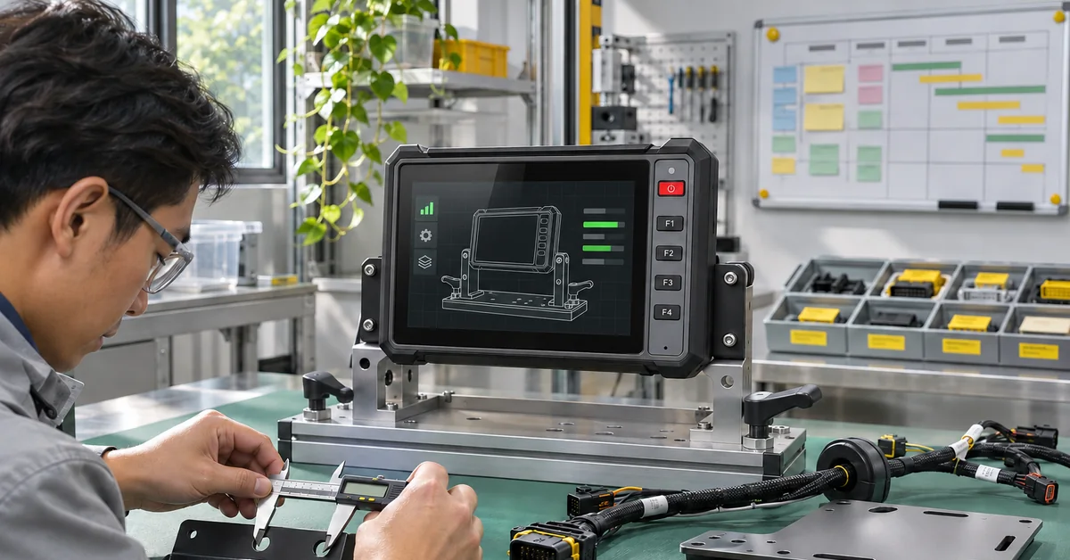

Vehicle Terminal ACC Test: Ignition and Shutdown
"It comes back when I turn the key again." That is a useful starting point for a fault report, but there are several possible faults behind it. The computer might have lost its supply. It might have followed an ignition-off instruction. Or the application might have stopped while the computer stayed on.
This vehicle terminal ACC test is a way to sort out those possibilities. Have the wiring documents for your actual terminal and vehicle open as you work through it. There isn't a pin number or an ignition threshold here that you can copy into every installation.

Two wires, two different questions
On the test drawing, label the main feed and ACC separately. Main feed answers "does the computer have power?" ACC answers "what ignition state is the computer being told about?" A fuse or sound ground connection cannot be replaced by an ACC signal.
Consider two possible results. In the first, the computer reboots while the engine is being started. ACC remained valid but the main input fell outside the approved condition. Calling this an "ACC failure" would be misleading. In the second, the supply remained present and the log shows an ignition-off event. The same visible symptom now needs a different investigation.
Which limits apply to your trace? PDS construction and mining material includes a 9-36V supply reference. It should not become the pass criterion for every SKU, every ignition input or every short disturbance. Where the project specification is silent, ask the product team before deciding that a trace has passed.
The photograph comes before the repair
The temptation is to reseat the connector and try again. Wait until the vehicle has been made safe, following its approved procedure, and take the photographs first. You want the loose lock, the ground point as found and the route as it was, including the fuse. A neat "after" picture can't recover those details.
A useful cover sheet has these fields:
- Vehicle and battery arrangement; terminal part number and hardware revision.
- Harness part number, drawing revision and pinout.
- OS and application builds, plus any external power controller.
- Connected cameras, receiver, modem and other loads; their power sources.
Leave room for notes. "Modem uploading; cameras on the shared branch" tells the next technician more than "normal load." Beside a retest, an entry such as "harness unchanged; application build changed" is equally helpful. Now the reader knows what stayed put.
What to capture during starting
The measurement point matters. A reading across the battery does not include the voltage lost between the battery and the terminal. For this investigation, obtain the main-input and ACC records at the terminal using approved test connections. Qualified personnel should choose and secure those connections before running the engine.
A meter can help with the initial key-state checks. A very brief event calls for a different conversation: how short an event can this instrument capture with these settings? The engineer choosing the recorder or oscilloscope needs to answer that before the run. Save the settings too, including sampling, range and ground reference. A trace on its own doesn't answer that question.
Start recording with the key off. Leave the recorder running through key-on without starting, the crank and engine-running state. ACC and main input need a common time base; line up the boot log with them. Three unrelated clocks would leave the reviewer guessing whether the restart came before or after the change.
No explanation in the trace? Leave that question open. There may be a software issue, a configuration issue or an electrical event the setup missed. "Nothing captured" is an honest result; "electrics proved good" is a much bigger conclusion.
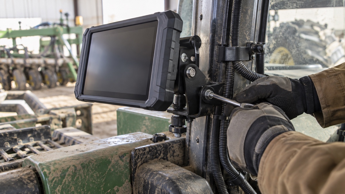
The screen went dark. What stopped?
Use the working application for the shutdown run. An empty desktop leaves out the file writes, camera work or upload queue that matter to the project. At key-off, note the time, the last completed application record and what the shutdown log reports.
Then compare what happened with the requirement. Perhaps the display should sleep while a modem finishes an upload. Perhaps the agreed sequence requires all those functions to stop. What would count as a fault on one vehicle may be exactly what was requested on another.
Try the documented offline case too. After the next boot, find the record that was in progress and compare the queue with what reached the receiving system. Missing data and duplicated data both deserve an issue entry. A photograph of a dark screen cannot settle either question.
Main power interrupted: a separate run
There are two quite different entries you might find in a test notebook: "key turned off, main feed left connected" and "main feed interrupted at the approved test point." Keep them separate. The interruption belongs in its own run, and only if the project calls for it and provides an approved method.
Imagine an upload was pending at that moment. After the computer comes back, the useful evidence is the queued record and what reached the server. Seeing the startup screen tells you little about the upload. The configuration, clock and last saved work also need a look; any manual recovery belongs in the notes.
That is why a bare promise of "power-fail safe" is difficult to test. Safe for which work? A partially written record, a saved setting and an upload already in progress aren't interchangeable. Settle the expected recovery with the application team while there is still time to change the acceptance sheet.
Keep the failure beside the successful retest
A folder containing only successful traces is missing half the story. Suppose the approved correction was a harness change. Keep the trace from the original harness, the drawing revision for the replacement and the new run together. Someone reviewing the work next month should be able to see what prompted the change.
How many more starts? Use the agreed acceptance plan, not a number borrowed from a different vehicle. A slow start still goes into the notebook, as does a run rescued by a manual restart. Between cycles, give the unit time to reach the state the next test assumes. Rushing into the next cycle can change the test itself.
Mechanical findings belong here when they affect the wiring. For related background, see the PDS wide-voltage and vibration guide. A loose lock, moving bracket or cable under tension is worth documenting even when the next electrical run passes.
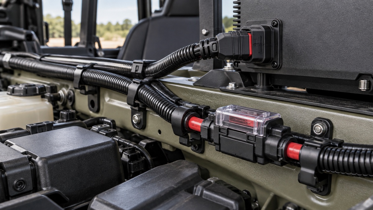
Vehicle terminal ACC test handover sheet
| Record | Attachments | Reviewer needs to establish |
|---|---|---|
| Installed build | Drawing, revisions, connector and ground photos | Which physical and software configuration was tested |
| Engine start | ACC and main-input traces; boot log | The sequence immediately before the restart |
| Key-off | Shutdown log, last record and low-power observation | Whether the required sequence completed |
| Interrupted feed | Interruption details and recovery inspection | What survived and what required recovery |
| Retest | Change description, new run and remaining issues | What the change actually resolved |
For model selection, compare the T10B and the PDS product range with the ignition behavior your application needs. Send the drawing and requirement with an enquiry. They are more useful than asking whether the computer "supports ACC" without explaining the shutdown expected.
FAQ
Can ACC supply the computer?
Use the wiring documentation for the selected model. In this test, ACC is the ignition-state input; it does not replace the specified main feed, ground or protection.
Must every start be recorded at the battery too?
The test plan should specify the required channels. A battery reading can help explain the upstream condition, while a terminal measurement shows what arrived at the computer.
What if the display sleeps before the modem?
Compare that sequence with the agreed keep-alive requirement. It might be intentional. Verify the application result and low-power state rather than judging by the display alone.
Which result should engineering receive?
Send the failed run as well as any successful retest, with build details and the recovery action. Keep the original observations separate from the suspected cause.
Contact us
📧Email: [email protected]
📞Tel: +86 13421822024
🌐Website: www.szpds.com
Disclaimer
The information in this article is for reference only. PDS Technology Co., Ltd. assumes no responsibility for errors, omissions, or suitability of the content for specific applications. Product specifications are subject to change without notice. Buyers should verify all technical details with our team before use.
About PDS Technology
PDS Technology is a leading OEM/ODM manufacturer of high-precision RTK GNSS terminals and vehicle computers, serving agriculture, construction, mining, taxi, and logistics industries since 2011.
With 15+ years of automotive-grade R&D experience, we offer rugged, multi-OS (Android/Linux/OpenHarmony) devices featuring RTK centimeter-level positioning, IP66 protection, and AI-ready performance. Our IATF16949-certified factories have produced over 100,000 units deployed globally, holding 30%+ of China's agricultural auto-steering terminal market. We export to Japan, the US, UK, Turkey, Russia, and beyond.